You must have seen many LED flashlights in the market, mostly using white LEDs as they provide perfect brightness and light. LEDs are excellent for applications subject to frequent on-off cycling, unlike fluorescent lamps that burn out faster when cycled frequently or HID lamps that require a long time before restarting. You can quickly dim or strobe them. So in this tutorial, we are going to design a simple “LED Torch Circuit using CD4049 IC”
The LED lights up promptly, and a typical LED red light reaches full illumination in milliseconds. These mostly fail by fading over time rather than the abrupt burn-out of incandescent bulbs.

Hardware Components
The following components are required to make LED Torch Circuit
| S.No | Component | Value | Qty |
|---|---|---|---|
| 1. | Breadboard | – | 1 |
| 2. | Connecting Wires | – | 1 |
| 3. | Buffer/Inverter IC | CD4049 | 1 |
| 4. | Diode | 1N4007 | 2 |
| 5. | Resistor | 6.7K | 1 |
| 6. | Ceramic Capacitor | 0.1uF, 220uF | 1, 2 |
| 7. | Battery | 9v | 1 |
| 8. | LED | 5mm | 3 |
CD4049 Pinout
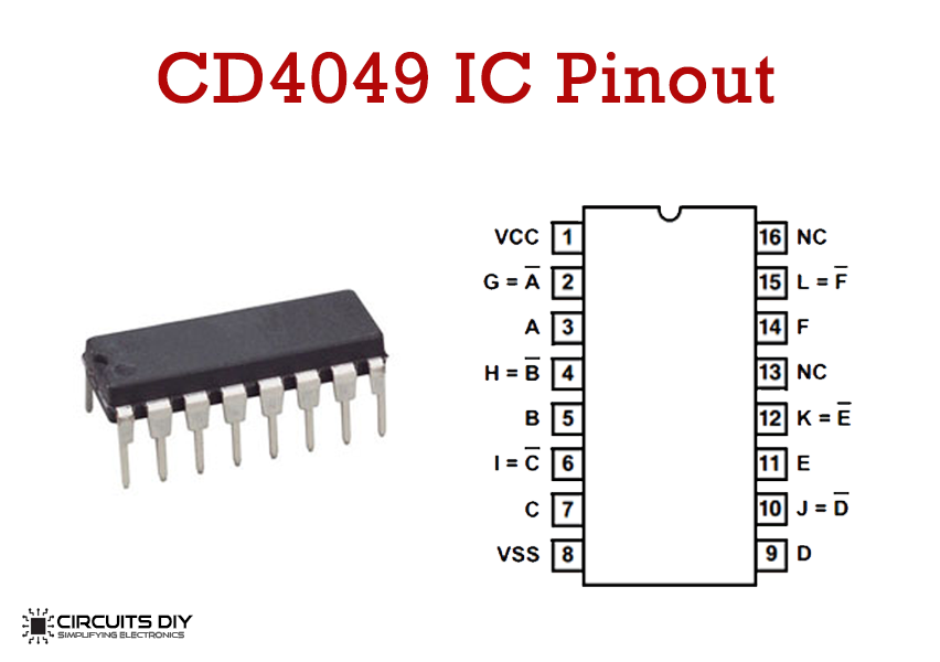
For a detailed description of pinout, dimension features, and specifications download the datasheet of CD4049
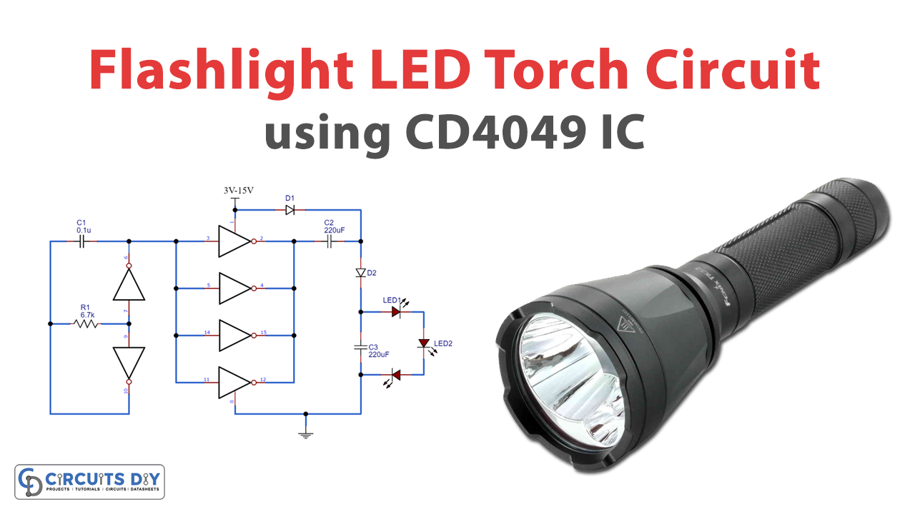
LED Torch Circuit

Working Explanation
We supply 5V DC voltage to the circuit. In the circuit, you arrange the resistor R1 and capacitor C1 with two NOT gates to make the oscillator circuit. The remaining 4 NOT gates connected in parallel form a buffer and twice the input voltage. As you turn on the supply capacitor, C2 starts charging, via a buffer made by four not gates, until the peak of the input voltage (5V). And now C2 acts as a second power source of 5V, so with the D1 and D2 forward biased, capacitor C3 charges with combined voltages of the power supply and the capacitor C2. Therefore, with the combined voltage of both, the capacitor C3 charges up to almost 10V.
The output voltage is enough to glow three white LEDs, and we have a Bright LED Torch.
Applications
- CMOS to DTL/TTL Hex Converters
- High sink current for driving two TTL loads
- Convert logic level from high to low

