Introduction
Music has been an integral part of human culture for centuries, and it has continued to evolve with the advancement of technology. In particular, electronic instruments have revolutionized how we create and enjoy music. Among these instruments, the electronic organ holds a special place.
It provides an easy and accessible way for anyone to create beautiful music. This blog will take a closer look at the technology behind electronic organs, how they work, and how you can build your own.
Hardware Required
| S.no | Components | Value | Qty |
|---|---|---|---|
| 1 | Transistor | 2N2926, 2N2646 | 1, 1 |
| 2 | Resistor | 10k, 4.7k, 39, 33k, 1.8M | 1, 1, 1, 2, 1 |
| 3 | V. Resistor | 2k, 10k | 1, 1 |
| 4 | Switch | – | 2 |
| 5 | Polar Capacitor | 50uF | 1 |
| 6 | Non Polar Capacitor | 0.1uF, 3000pF, 0.05 | 2, 1, 3 |
Circuit Diagram

Overview
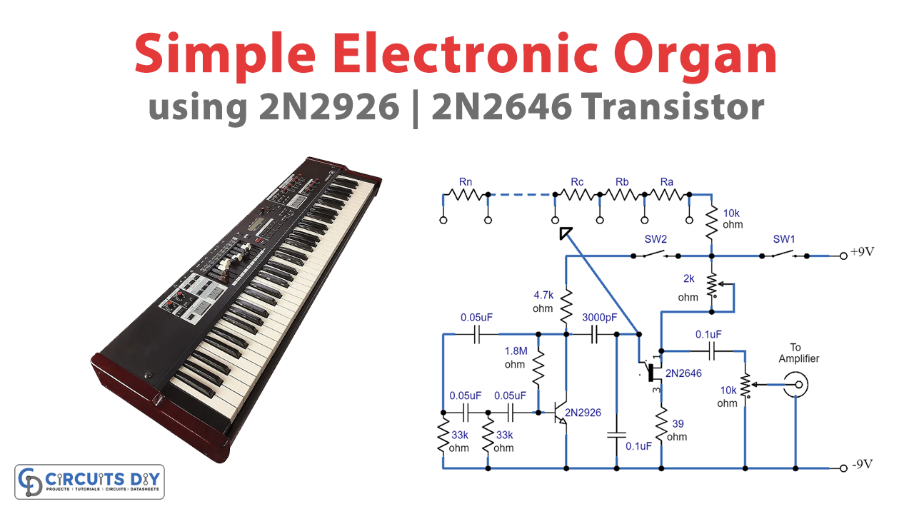
Electronic organs are complex and costly devices that generate basic notes using tone generators and provide a wide range of instruments through “voicing.” However, building a simple organ using a straightforward electronic circuit is possible. This circuit has an advantage over others as there is no complex set-up procedure, making it easier to use.
The circuit consists of a tone generator and a vibrato unit that we can build separately. A probe is used to select the correct notes, and the note’s frequency depends on the resistance in that chain. A low-frequency signal, called vibrato, can be added to the note to give it character. The oscillator is a phase-shift type, and the output is taken from the collector to the emitter of the uni-junction. The organ’s range can be extended by adding further resistors, but these need to be found by experiment. The circuit consumes a low amount of current and can be powered by a PP3 battery.
Construction and Battery Consumption
Construction can take any form, but it is essential to note that the probe cannot be metal. Various probes can be tried until one that instantly makes a nice, clean note is found. The circuit consumes a low amount of current and can be powered by a PP3 battery.
Tone Generator
The tone generator comprises a unijunction transistor type 2N2646, C5, R5, VR1, and the tone resistors. The emitter of the unijunction goes to a probe which can select the correct notes. The frequency of the note depends on the total resistance in that chain, and VR1 is preset that alters the whole range. The output is taken from the oscillator via C6 to the volume control, which should be connected to an external amplifier. The circuit will produce the correct notes but may lack character and pleasantness.
Vibrato Unit
The vibrato unit works at a frequency that will lie in the range of 10Hz to 30Hz and raises and lowers the output level very slightly at this frequency. This stage can be built separately and mixed with the note to add character. It is strongly recommended to fit this stage.
Oscillator
The oscillator is a phase-shift type, and the output is taken from the collector via C4 to feed directly to the emitter of the unijunction. The low-frequency note is not heard when the probe is not selecting a note. Phase-shift oscillators can sometimes be troublesome, but a slight change in the value of R3 usually cures the problem.
Final Words
Electronic organs are fun to play and a great way to learn the basics of music theory. With the help of modern technology, building an electronic We hope this blog has inspired you to explore the fascinating world of electronic organs and given you some valuable insights into how they work. Now, it’s time to get creative and start building your own!


