If you are a student who has to make electronic projects, or someone who has to make them on a daily basis or repair electronic circuits then the most important tool on your bench is a continuity tester.
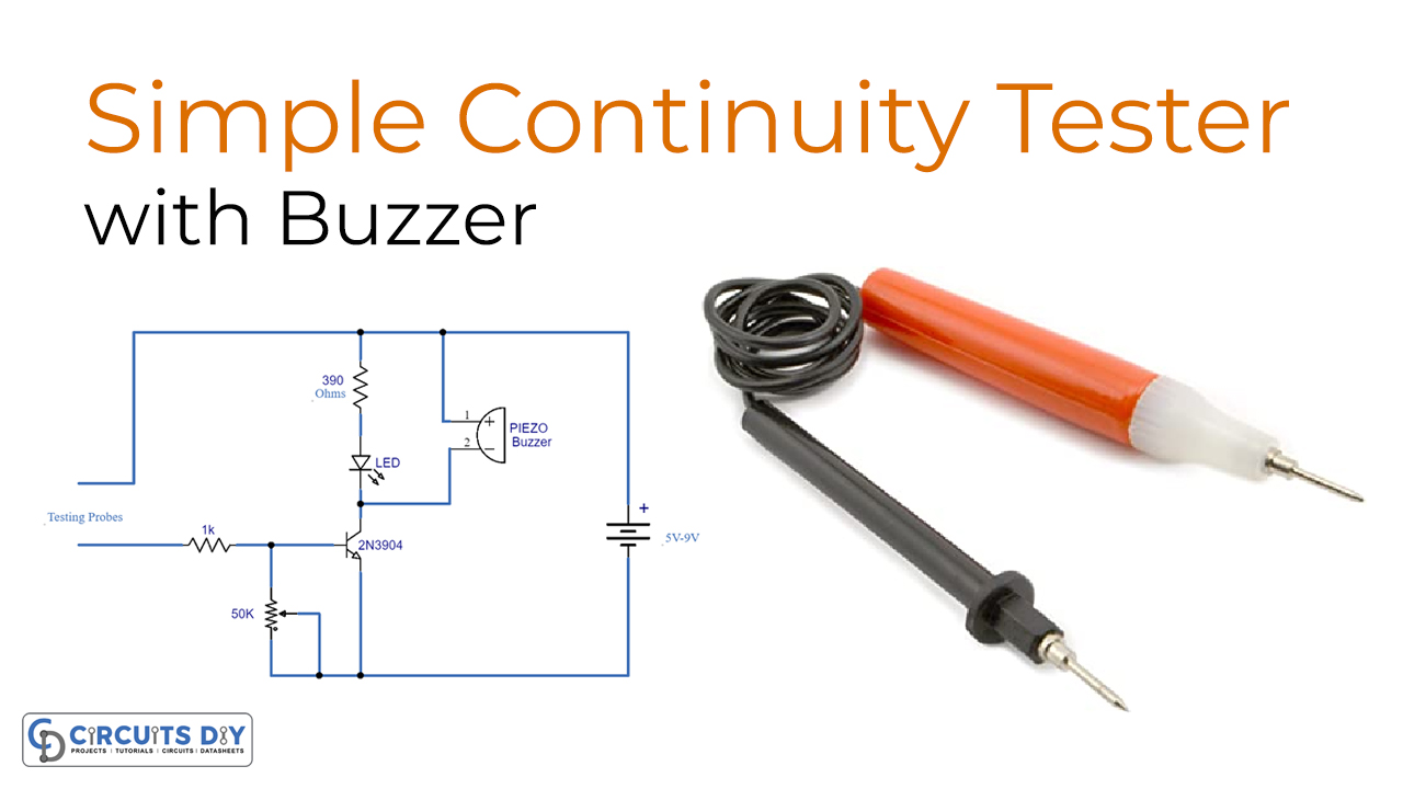
A continuity tester is a device that checks and identifies a connection between two points. it checks the connection and lets us know if the connection or wire on the PCB is broken or the circuit is open due to failed components. This circuit is quite simple and highly sensitive, it is only using a few components that are commonly available and perform accurately.
Hardware Components
The following components are required to make the Continuity Tester Circuit
| S.no | Component | Value | Qty |
|---|---|---|---|
| 1. | Input Supply DC | 5-9V | 1 |
| 2. | Probes | – | 1 |
| 3. | Resistor | 1K, 390 | 1, 1 |
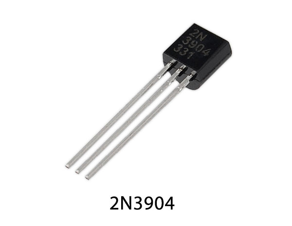
| 4. | Transistor | 2N3904 | 1 |
| 5. | LED | – | 1 |
| 6. | Piezo buzzer | – | 1 |
| 7. | Variable Resistor | 50K | 1 |
2N3904 Pinout
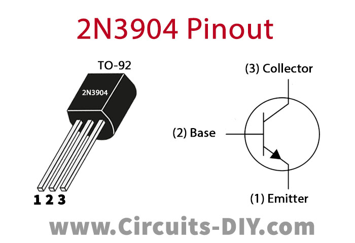
For a detailed description of pinout, dimension features, and specifications download the datasheet of 2N3904
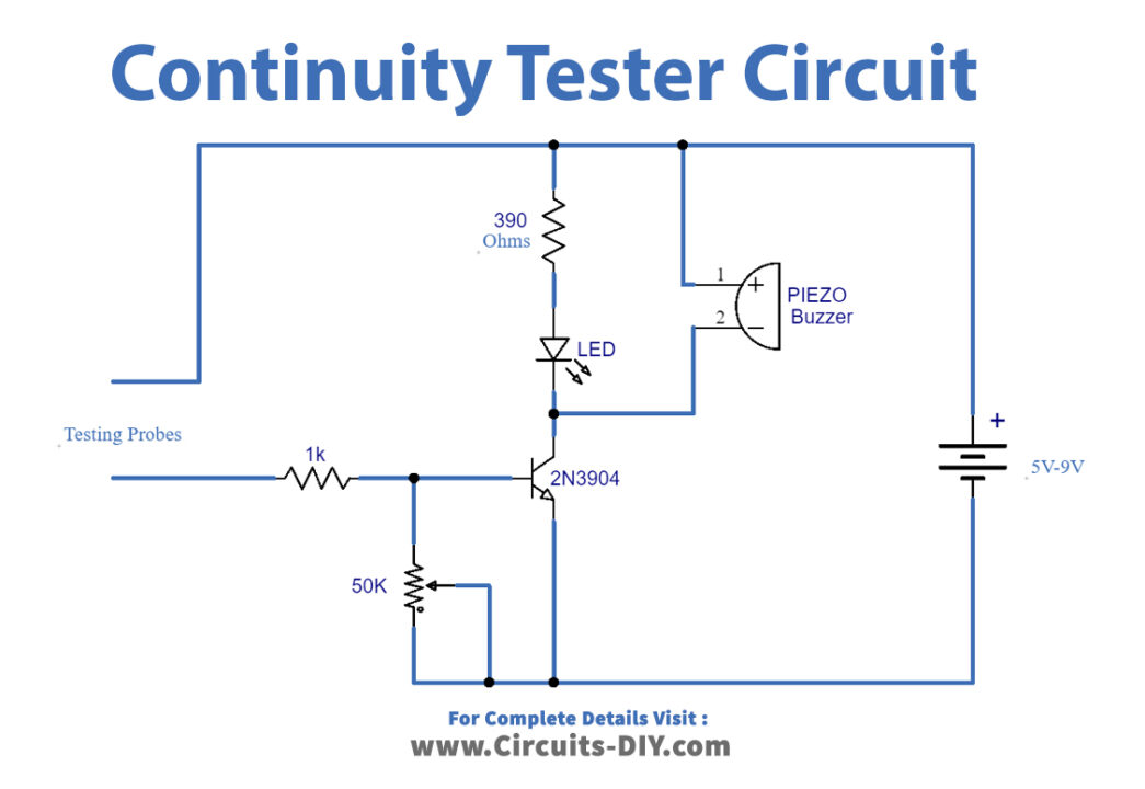
Continuity Tester Circuit
Working Explanation
The operating voltage of this circuit is 5 to 9 volts DC. Two testing probes are used that are placed on the circuit’s component or the wire. These probes will detect whether there is a connection or something is broken. Then they send a signal to the transistor 2N3904 that is acting as a switch here. When the transistor activates it will activate the LED and the piezo buzzer connected at the output to show the visual and audible indication of a good connection. A buzzer is a very important element of this continuity tester because you will know and identify a connection while checking the faulted circuit by hearing the buzzer sound so you don’t have to look at the tester itself frequently. To adjust the sensitivity of the circuit we have used a 50K variable resistor.
Applications and Uses
- Electronic laboratories
- Industrial applications
- Small or big electronic circuits
- Electronic appliances


