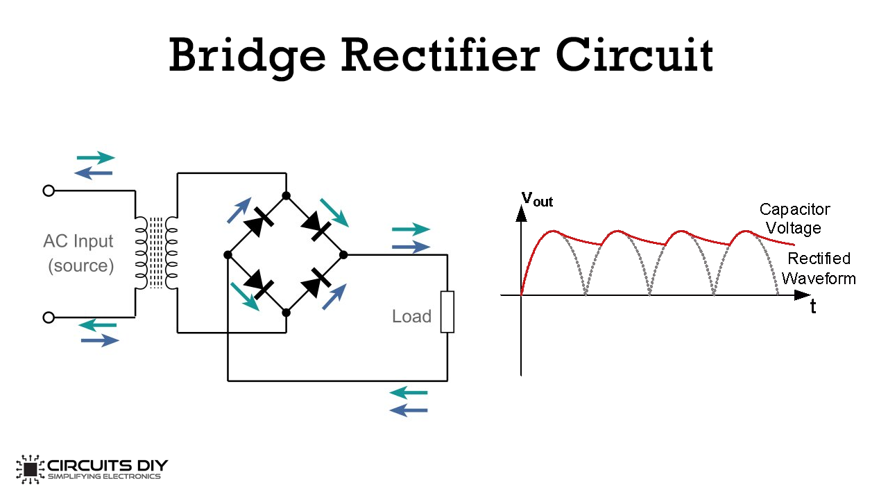
Simple Bridge Rectifier Circuit is used to convert the alternating current (AC) into direct current (DC). The process of converting AC into DC is known as Rectification. There are two types of Rectification, Half-wave rectification, and Full-wave Rectification. To make the direct current (DC) useful we further use filtration by using capacitors at the end node.
Types of Rectifiers:
- Half-wave Rectifier: Half wave rectifier converts only one half of the alternating current into direct current
- Full-wave Rectifier: Full-wave rectifier converts both halves of the alternating current into direct current
Types of Full-wave Rectifiers:
- Center-tapped full-wave rectifier
- Bridge rectifier
Working:
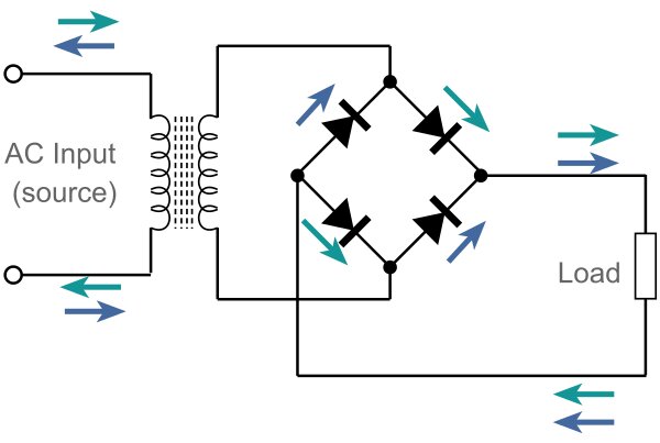
When the positive half of the alternating current comes, it passes through two diodes and reaches to the load as positive to negative end (Shown in light blue). When the negative half of the alternating current comes if passes from the other two diodes and reaches the load in the same flow (shown in dark blue). Hence the alternating current converted into direct current.
Hardware Components for Bridge Rectifier Circuit:
| S.NO | Component | Value | Qty |
| 1. | Breadboard | – | 1 |
| 2. | Transformer | 230vAC | 1 |
| 3. | Diode | 1N4007 | 4 |
| 4. | Resistor as a Load | 1k ohm | 1 |
| 5. | Connecting wires | – | 1 |
Filtration:
The output we get from the bridge rectifier is not proper direct current that is why we need to smooth it making proper direct current by filtering. Filtering is done by the capacitor places just after the bridge output.