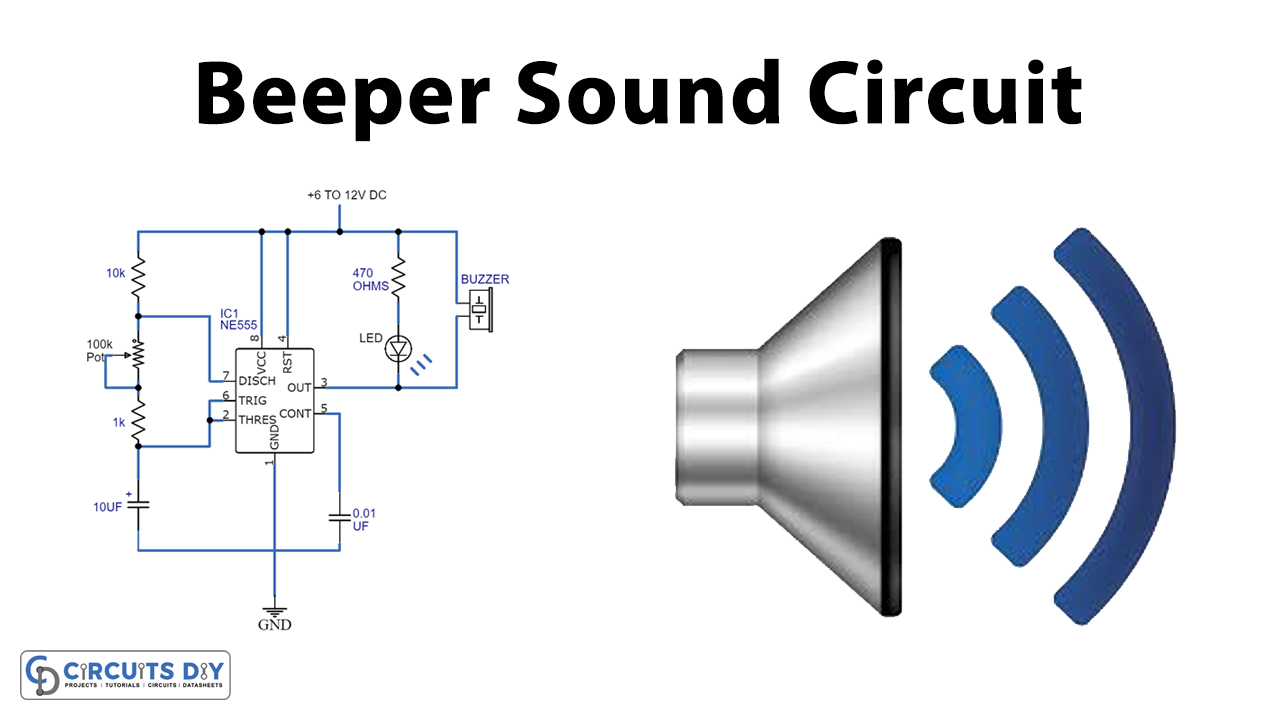
A beeper Circuit is a small circuit that produces a Beep-Beep sound. The simple circuit involves a NE555 timer IC that drives a buzzer and LED with the help of a variable resistor-capacitor network.

Hardware Components
The following components are required to make Beeper Sound Circuit
| S.no | Component | Value | Qty |
|---|---|---|---|
| 1. | Breadboard | – | 1 |
| 2. | Battery | 9v | 1 |
| 3. | Connecting Wires | – | 1 |
| 4. | IC | NE555 Timer | 1 |
| 5. | Piezo Buzzer | – | 1 |
| 6. | Resistor | 470Ω, 1KΩ, and 10KΩ | 1,1,1 |
| 7. | Variable Resistor | 100KΩ | 1 |
| 8. | Capacitor | 10µF, 0.01µF | 1,1 |
| 9. | LED | – | 1 |
NE555 IC Pinout

For a detailed description of pinout, dimension features, and specifications download the datasheet of 555 Timer
Beeper Sound Circuit

Working Principle
A NE555 IC is a timer IC that produces accurate oscillation and time delays. Furthermore, the resistor and capacitor network in the circuit allows the change in interval timings. Also, the frequency and duty cycle are controllable using a capacitor and a variable resistor network.
The NE555 IC in this circuit is operated as an astable multivibrator where NE555 produces highly accurate waveforms along with the adjustment of the output frequency. The Pin configuration of the IC is such that PIN 01 and PIN 08 are the ground and positive terminals, respectively. PIN 02 and PIN 06 are such that they perform the re-triggering operation allowing each and every cycle to repeat itself, hence, acting as a running oscillator. On the other hand, PIN 03 is the output of the IC that drives the piezo buzzer and LED. The re-triggering process allows the ON and OFF operation of both the buzzer and the LED. Additionally, the output is controlled by a variable resistor of 100KΩ.
To operate the circuit with a low voltage of 6V, replace a current limiting resistor with LED and a 470Ω with a 330Ω resistor.
Application
- Used as a sidelight indicator in a vehicle
- Applicable in household appliances such as a microwave oven.
- Used in sporting events.


