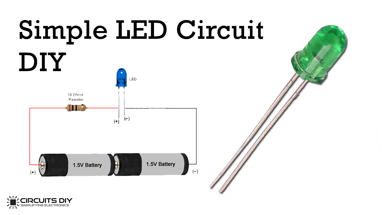
Building a basic LED circuit is the very first stepping stone for every electronic enthusiast, hobbyist & student. It is probably the first circuit anyone makes when they interact with electronics for the first time. So, in this project, we will review the basics & will understand the working principle of a Basic LED circuit corresponding to different supply voltages.
This is a very simple electronic circuit requiring only three elements: an LED, a voltage source & a current-limiting resistor corresponding to the said voltage source. Here, we will understand the value of various current limiting resistors with respect to 3V, 6V, 9V & 12V supplies.
Hardware Components
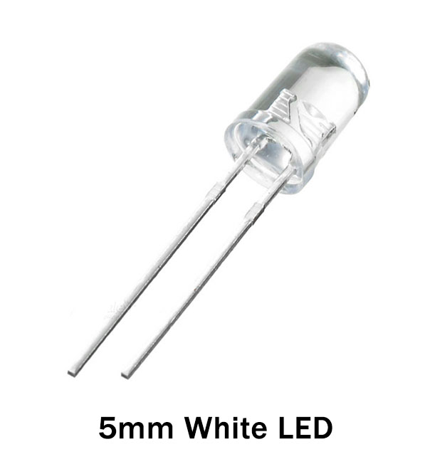
The following components are required to make a Simple LED Circuit
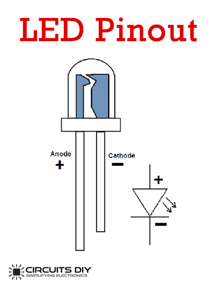
LED Pinout
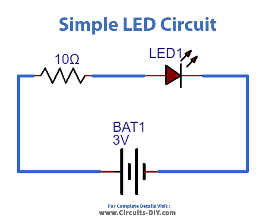
LED Circuit
Working Explanation
The circuits above show the setup of LEDs connected to 3V,6V,9V & 12V Supply along with their respective current limiting series resistor. The important component (other than the LED of course) is the Resistor. Connecting a small LED directly to the Supply without any current limiting resistance would burn the LED instantly.
A current limiting resistor is used to provide the accurate required current to the LED, connecting the LEDs directly to the battery or power supply will damage them & shorten their life. Above are the four basic led circuits, in these circuits, a single LED is operated with four different supply voltages using different current limiting resistors with each battery. If you want to operate your LED with other voltages like such as 4V, 5V, 7V, 8V & 14V, etc. then you have to find a suitable resistor for these voltages with the help of an LED resistor calculator.
Applications
- Its common use is to serve as an indicator or digital display for devices such as LED TVs, alarms, etc.
- Very useful due to inherent properties such as very low power consumption, long life, cheap & reliable circuit


