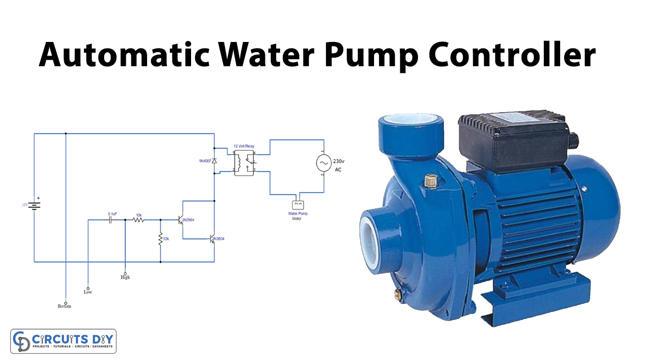
The article portrays a basic and economical “automatic water pump controller” circuit. A “water pump controller” detects the level of water in a tank and drives the water pump. The controller controls the output and speed of the pump. The input factors are given by different sensors, for example, level sensors and flow meters. At that point, data triggers the pump controller, which at that point changes the speed of the pump to the optimal.
The three probes are used to detect the water level in the circuit, and consequently turn ON the pump on the ideal low degree of water and automatically switch it OFF on the ideal elevated level of water.
Hardware Components
The following components are required to make an Automatic Water Pump Controller Circuit
| S.no | Components | Value | Qty |
|---|---|---|---|
| 1. | Relay | 12V | 1 |
| 2. | Water Pump Motor | – | 1 |
| 3. | Diode | 1N4007 | 1 |
| 4. | Transistor | 2N3904 | 1 |
| 5. | Ceramic Capacitor | 0.1µF | 1 |
| 6. | Resistor | 10K, 33K | 1, 1 |
| 7. | DC Supply | 12V | 1 |
| 8. | Water Level Probes | – | 3 |
2N3904 Pinout
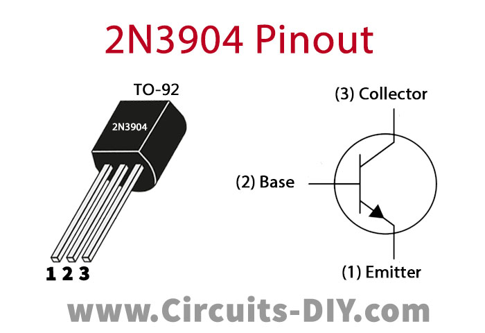
For a detailed description of pinout, dimension features, and specifications download the datasheet of 2N3904
Automatic Water Pump Controller Circuit
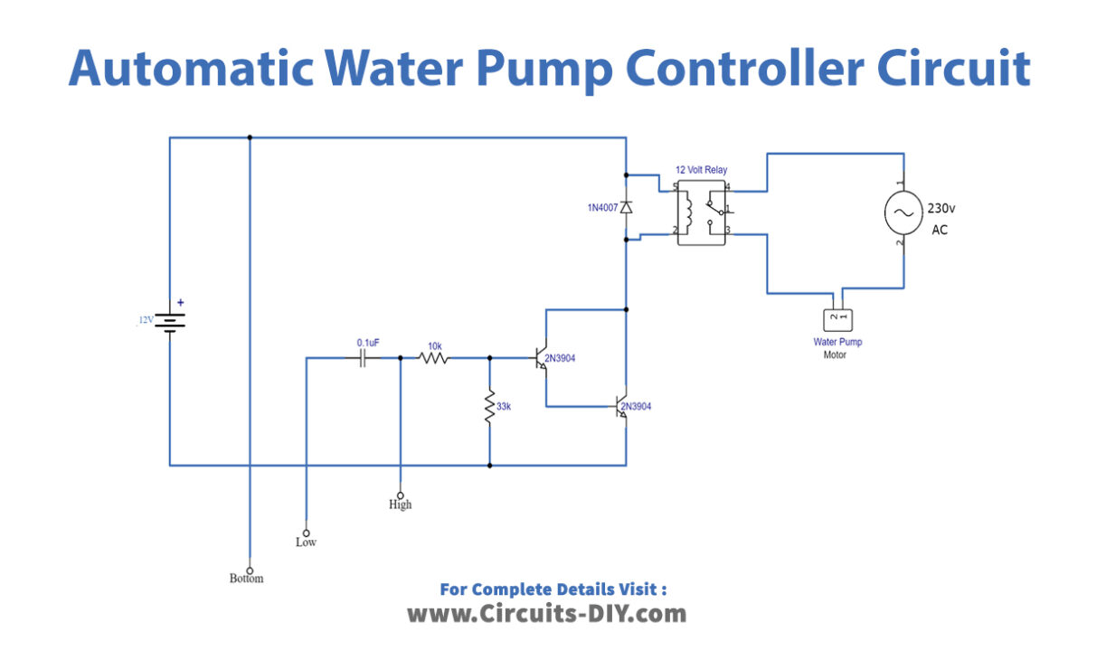
Working Explanation
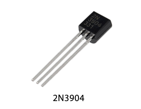
The circuit is utilizing just two 2N3904 transistors and some other low-cost components. The 2N3904 is an “NPN bipolar junction transistor” used for general use for low-power switching or amplifying purposes. We are using an “electrically operated switch”.
The three probes are utilized in the circuit which is ought to be set as marked in the schematic, the base probe ought to be set at the base of the tank, and the probe checked “Low” ought to be set on the ideal level on which actuation of the pump is required and probe marked “High” ought to be set at the level where you need to stop the pump. The Working voltage of the circuit is 12V DC.
Applications and Uses
These types of water pump controllers can use in:
- Swimming Pools
- Water Tanks
- Pumps, etc.


