Ever wondered how come you can just simply tune in to your favorite FM Radio Channel? Moreover, ever had the curiosity of making your own FM Station on a specific frequency? Well if the answer is Yes to any of those questions then you are at the right place! We are going to look into making a small FM Transmitter for Hobby Purposes with a really basic component guide and components that are readily available off the shelf.

Hardware Components:
The following components are required to make FM Transmitter Circuit
| S.no | Component | Value | Qty |
|---|---|---|---|
| 1. | Antenna | 12 Inch | 1 |
| 2. | Transistor | 2N3904 | 1 |
| 3. | Electret Mic | – | 1 |
| 4. | Battery | 9V or 12V | 1 |
| 5. | Ceramic Capacitor | 0.47uF, 1nF, 39pF, 5pF | 1,1,1 |
| 6. | Inductor | 1uH | 1,1 |
| 7. | Resistors | 1k, 10k, 5.5k | 2,1,1 |
2N3904 Pinout

For a detailed description of pinout, dimension features, and specifications download the datasheet of 2N3904
FM Transmitter Circuit

Working Explanation
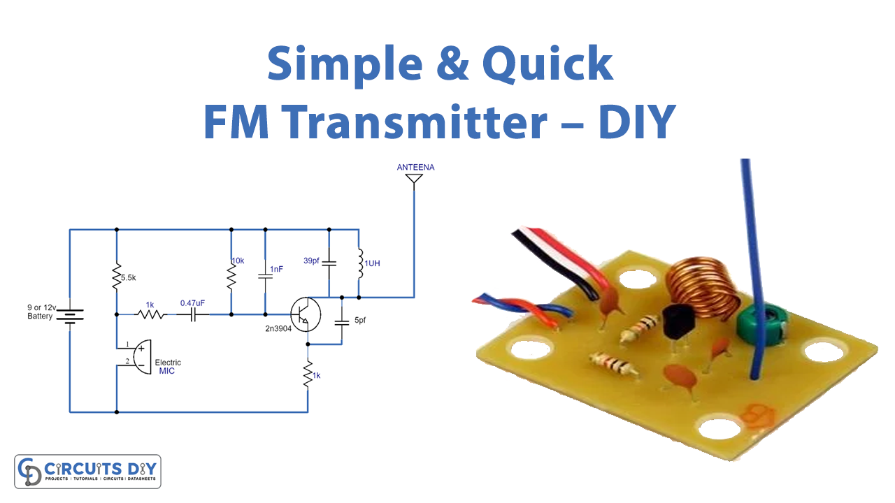
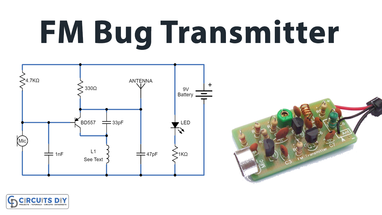
The major game here is the Antenna and the Mic. The Mic converts sound waves into an electrical voltage which is filtered via a resistor-capacitor network and amplified using the 2N3904 Transistor. The amplified signal is then transmitted for propagation via the antenna. You might be wondering why there is an inductor near the antenna, this goes into the field of antenna-matching circuitry.
Applications & Uses:
- Small Range Walkie Talkies.
- Transmitting Digital Signals (with few modifications).
- Make your own Mini FM Radio Station.

