If you want your room lights to be according to your mood then you need to adjust them with a controller. Here in this article, you will learn to construct a 12V Lamp Dimmer in the easiest way with minimal components.
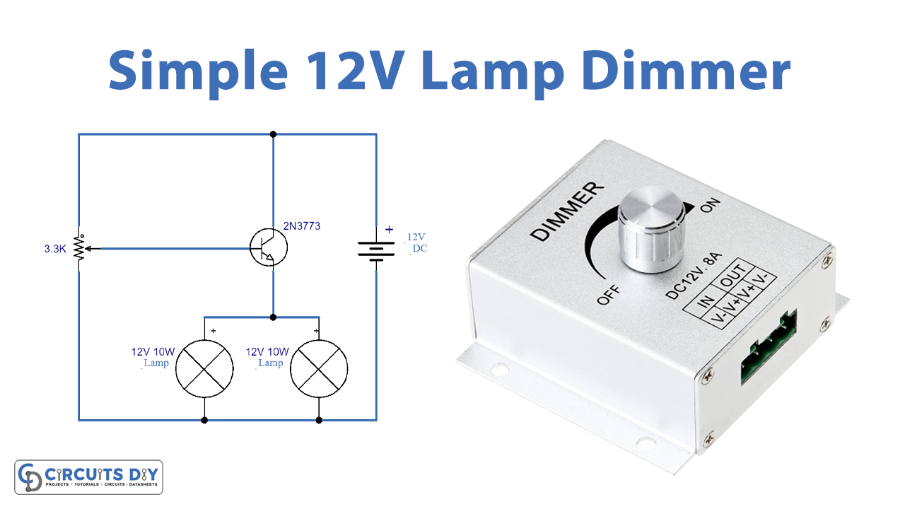
The 12V Lamp dimmer circuit is a simple electronic circuit that helps to control the light intensity i.e. the brightness of a 12V bulb. It uses a variable resistor for its control with a transistor. These two components are the only elements that complete this circuit. This circuit is commonly practiced on switchboards placed at homes, offices, etc.
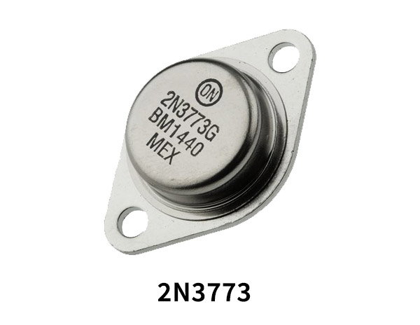
Hardware Components
The following components are required to make 12V Lamp Dimmer Circuit
| S.no | Components | Value | Qty |
|---|---|---|---|
| 1. | Transistor | 2N3773 | 1 |
| 2. | Lamp | 12V 10Watt | 1 |
| 3. | Heat Sink | – | 1 |
| 4. | Power Supply | 12V | 1 |
| 5. | Variable Resistor | 3.3K | 1 |
| 6. | Breadboard | – | 1 |
| 7. | Connecting Wires | – | 1 |
2N3773 Pinout
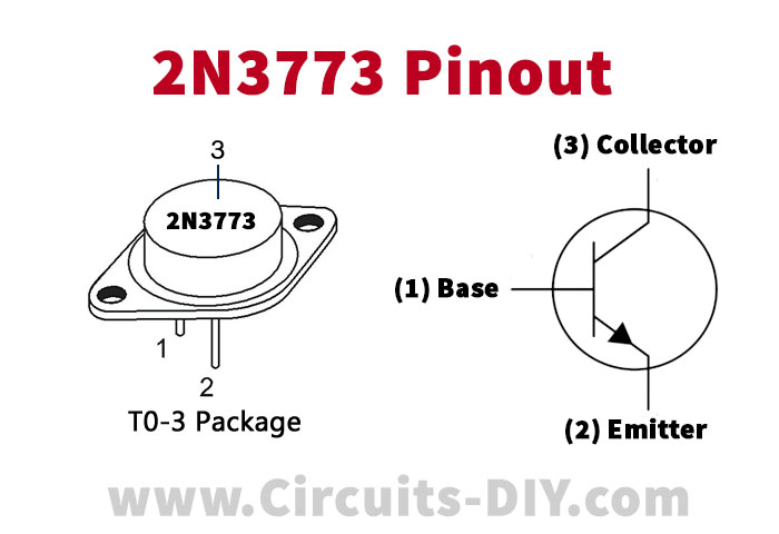
For a detailed description of pinout, dimension features, and specifications download the datasheet of 2N3773
12V Lamp Dimmer Circuit
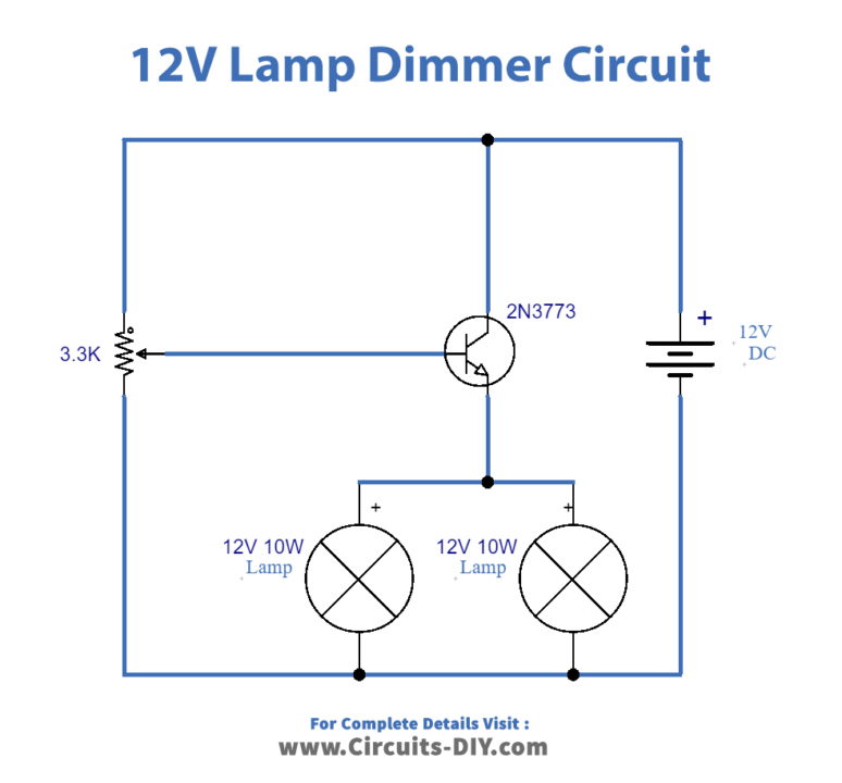
Working Explanation
This circuit has a simple working. 2N3773 transistor is used as a current controlling device. The small current at the base side helps to control the larger currents on the emitter and collector side. 3.3k variable resistor is managing the intensity of light. Therefore, by using these two main elements this circuit can work perfectly for your 12V bulb.
Applications & Uses
- It is mostly used in spas where dim lights are often used for relaxation
- This dimmer circuit also serves in restaurants where certain occasions need intense dinner settings


