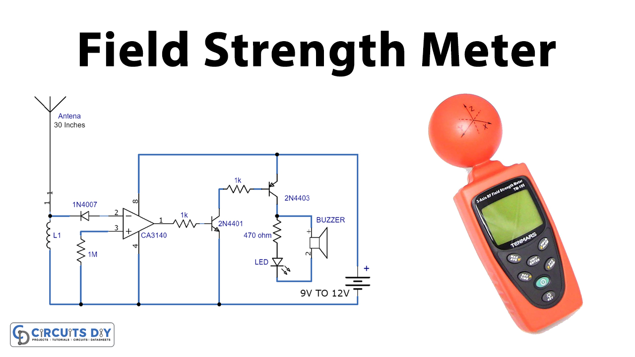
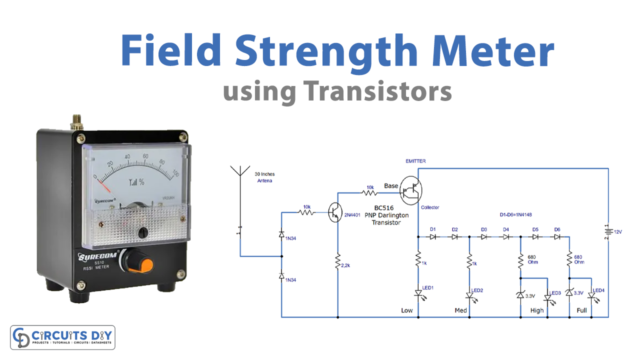
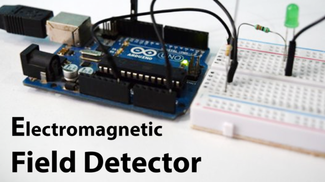
In this project, we are demonstrating the FM Field Strength Meter or RF detector circuit. This is a project of exceptionally sensitive FM field strength meters or we can likewise say them RF detectors. A radio frequency (RF) detector is a device used to detect the RF waves either in a wireless or wired (on RF Cable) physical transmission medium. Both the circuits can be utilized to quantify the field or signal quality of FM transmitters.
The circuits are very sensitive and can recognize a low-power transmitter from 8 to 10 meters away and give a visual and sound signal by actuating an LED and a piezo buzzer.

Hardware Components
The following components are required to make RF Detector Circuit
| S.no | Components | Value | Qty |
|---|---|---|---|
| 1 | IC | CA3140 | 1 |
| 2 | PNP Transistor | 2N4403 | 1 |
| 3 | Piezo Buzzer | – | 1 |
| 4 | Diode | 1N4007 | 1 |
| 5 | Antenna | 30 Inches | 1 |
| 6 | LED | – | 1 |
| 7 | Coil | 6 turns | 1 |
| 8 | Resistor | 1M, 470Ω, 1K | 1, 1, 2 |
| 9 | Battery | 9 – 12V | 1 |
| 10 | NPN Transistor | 2n4401 |
CA3140 Pinout
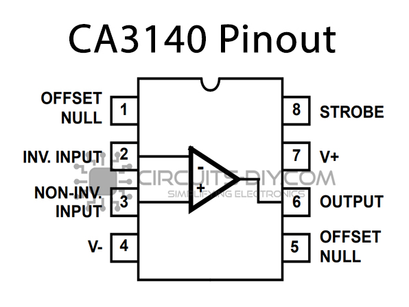
For a detailed description of pinout, dimension features, and specifications download the datasheet of CA3140
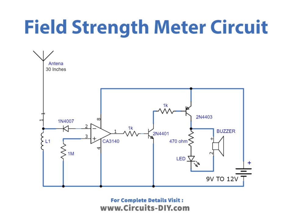
RF Detector Circuit
Hardware Components
The following components are required to make Field Strength Meter Circuit
| S.no | Components | Value | Qty |
|---|---|---|---|
| 1 | CA3140 | CA3140 | 1 |
| 2 | Transistor | 2n3904 | 1 |
| 3 | Battery | 9 – 12V | 1 |
| 4 | Piezo Buzzer | – | 1 |
| 5 | Diode | 1N4007 | 1 |
| 6 | Antenna | 85 cm | 1 |
| 7 | LED | – | 1 |
| 8 | Coil | 6 turns | 1 |
| 9 | Resistor | 1K, 1M, 470Ω | 1, 1, 1 |
Field Strength Meter Circuit

Circuit Operation
In this section, we have discussed the circuit operation of the FM Field Strength Meter. The field strength meter or RF detector circuit has appeared in figure 1 is a basic circuit utilizing not more than 8 segments and a battery. The circuit is worked around a CA3140 IC, which is an operational amplifier. There isn’t a lot of difference between the two circuits yet just the 2N3906 PNP transistor utilized at the output of the figure 2 circuit to additionally increase the sensitivity. L1 is an air-cored coil and can be made effectively by winding 6 turns of #24 enameled wire on a 5mm structure. Make sure to expel the insulation from the two parts of the enameled wire to make a solder connection. For radio, wire utilizes an 85 centimeters adjustable antenna.
Applications and Uses
There are many applications for FM Field Strength Meter or RF detector but primarily it is used to measure and control RF power in wireless systems.


