Introduction
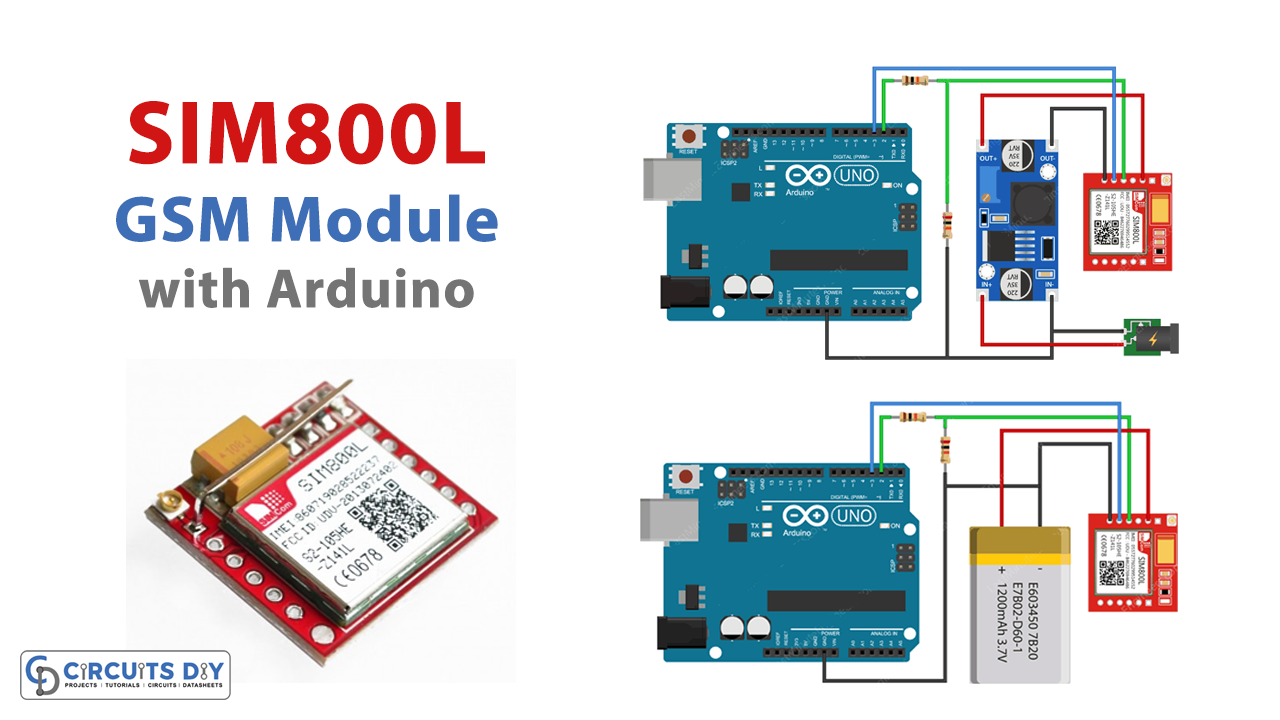
To allow your device to send and receive a message or to enable any device to make or receive a call, there are some modules in the electronics market. SIM800L is one of those modules that helps the user to interact with mobile phones by sending or receiving updates. Hence this compact and portable device can be integrated with many IoT devices. Moreover, it also allows the user to connect to the internet by the GPRS, IP, TCP, etc. Therefore, in this tutorial, we have decided to interface “Send Receive SMS & Call with SIM800L GSM Module with Arduino UNO”.
An Overview of the SIM800L Module
The module contains the cellular chip of SimCom. The module has a Helical Antenna that gets soldered directly to the NET pin on the PCB. Also, it has a SIM socket that allows any micro 2G SIM card. Furthermore, the module uses the AT command to start the communication. The module holds the LED on the top right side which shows the status of the network. Hence, the LED blinks at various rates to indicate the states.

Hardware Required
| S.no | Components | Value | Qty |
|---|---|---|---|
| 1 | Arduino UNO | – | 1 |
| 2 | USB Cable Type A to B | – | 1 |
| 3 | Jumper Wires | – | – |
| 4 | GSM/GPRS module | SIM800L | 1 |
| 5 | Resistor | 1K | 2 |
| 6 | Adapter | 5v | 1 |
| 7 | Li-Battery | 3.7v | 1 |
| 8 | DC-DC Buck Converter Power Module | LM2596HV | 1 |
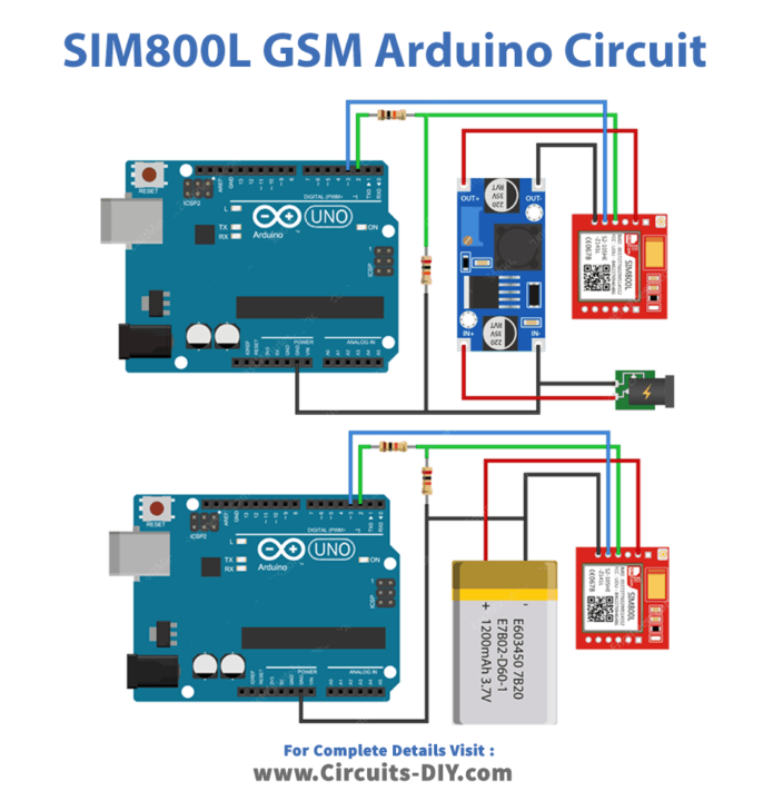
Circuit Diagram
Arduino Code
Testing AT Commands
#include <SoftwareSerial.h>

//Create software serial object to communicate with SIM800L
SoftwareSerial mySerial(3, 2); //SIM800L Tx & Rx is connected to Arduino #3 & #2

void setup()
{
  //Begin serial communication with Arduino and Arduino IDE (Serial Monitor)
  Serial.begin(9600);

  //Begin serial communication with Arduino and SIM800L
  mySerial.begin(9600);

  Serial.println("Initializing...");
  delay(1000);

  mySerial.println("AT"); //Once the handshake test is successful, it will back to OK
  updateSerial();
  mySerial.println("AT+CSQ"); //Signal quality test, value range is 0-31 , 31 is the best
  updateSerial();
  mySerial.println("AT+CCID"); //Read SIM information to confirm whether the SIM is plugged
  updateSerial();
  mySerial.println("AT+CREG?"); //Check whether it has registered in the network
  updateSerial();
}

void loop()
{
  updateSerial();
}

void updateSerial()
{
  delay(500);
  while (Serial.available())
  {
    mySerial.write(Serial.read());//Forward what Serial received to Software Serial Port
  }
  while(mySerial.available())
  {
    Serial.write(mySerial.read());//Forward what Software Serial received to Serial Port
  }
}
Arduino Code – Sending SMS
#include <SoftwareSerial.h>

//Create software serial object to communicate with SIM800L
SoftwareSerial mySerial(3, 2); //SIM800L Tx & Rx is connected to Arduino #3 & #2

void setup()
{
  //Begin serial communication with Arduino and Arduino IDE (Serial Monitor)
  Serial.begin(9600);

  //Begin serial communication with Arduino and SIM800L
  mySerial.begin(9600);

  Serial.println("Initializing...");
  delay(1000);

  mySerial.println("AT"); //Once the handshake test is successful, it will back to OK
  updateSerial();

  mySerial.println("AT+CMGF=1"); // Configuring TEXT mode
  updateSerial();
  mySerial.println("AT+CMGS=\"+ZZxxxxxxxxxx\"");//change ZZ with country code and xxxxxxxxxxx with phone number to sms
  updateSerial();
  mySerial.print("Last Minute Engineers | lastminuteengineers.com"); //text content
  updateSerial();
  mySerial.write(26);
}

void loop()
{
}

void updateSerial()
{
  delay(500);
  while (Serial.available())
  {
    mySerial.write(Serial.read());//Forward what Serial received to Software Serial Port
  }
  while(mySerial.available())
  {
    Serial.write(mySerial.read());//Forward what Software Serial received to Serial Port
  }
}
Reading SMS
#include <SoftwareSerial.h>

//Create software serial object to communicate with SIM800L
SoftwareSerial mySerial(3, 2); //SIM800L Tx & Rx is connected to Arduino #3 & #2

void setup()
{
  //Begin serial communication with Arduino and Arduino IDE (Serial Monitor)
  Serial.begin(9600);

  //Begin serial communication with Arduino and SIM800L
  mySerial.begin(9600);

  Serial.println("Initializing...");
  delay(1000);

  mySerial.println("AT"); //Once the handshake test is successful, it will back to OK
  updateSerial();

  mySerial.println("AT+CMGF=1"); // Configuring TEXT mode
  updateSerial();
  mySerial.println("AT+CNMI=1,2,0,0,0"); // Decides how newly arrived SMS messages should be handled
  updateSerial();
}

void loop()
{
  updateSerial();
}

void updateSerial()
{
  delay(500);
  while (Serial.available())
  {
    mySerial.write(Serial.read());//Forward what Serial received to Software Serial Port
  }
  while(mySerial.available())
  {
    Serial.write(mySerial.read());//Forward what Software Serial received to Serial Port
  }
}
Arduino Code – Making Call
#include <SoftwareSerial.h>

//Create software serial object to communicate with SIM800L
SoftwareSerial mySerial(3, 2); //SIM800L Tx & Rx is connected to Arduino #3 & #2

void setup()
{
  //Begin serial communication with Arduino and Arduino IDE (Serial Monitor)
  Serial.begin(9600);

  //Begin serial communication with Arduino and SIM800L
  mySerial.begin(9600);

  Serial.println("Initializing...");
  delay(1000);

  mySerial.println("AT"); //Once the handshake test is successful, i t will back to OK
  updateSerial();

  mySerial.println("ATD+ +ZZxxxxxxxxxx;"); //  change ZZ with country code and xxxxxxxxxxx with phone number to dial
  updateSerial();
  delay(20000); // wait for 20 seconds...
  mySerial.println("ATH"); //hang up
  updateSerial();
}

void loop()
{
}

void updateSerial()
{
  delay(500);
  while (Serial.available())
  {
    mySerial.write(Serial.read());//Forward what Serial received to Software Serial Port
  }
  while(mySerial.available())
  {
    Serial.write(mySerial.read());//Forward what Software Serial received to Serial Port
  }
}
Arduino Code – Receiving Call
#include <SoftwareSerial.h>

//Create software serial object to communicate with SIM800L
SoftwareSerial mySerial(3, 2); //SIM800L Tx & Rx is connected to Arduino #3 & #2

void setup()
{
  //Begin serial communication with Arduino and Arduino IDE (Serial Monitor)
  Serial.begin(9600);

  //Begin serial communication with Arduino and SIM800L
  mySerial.begin(9600);

  Serial.println("Initializing...");
}

void loop()
{
  updateSerial();
}

void updateSerial()
{
  delay(500);
  while (Serial.available())
  {
    mySerial.write(Serial.read());//Forward what Serial received to Software Serial Port
  }
  while(mySerial.available())
  {
    Serial.write(mySerial.read());//Forward what Software Serial received to Serial Port
  }
}
Working Explanation
Connect SIM800L GSM Module & Arduino according to the circuit diagram. Now, for the initialization of commands use AT command code and upload the code in Arduino IDE. Hence you will analyze the initialization of the commands on the serial monitor. Write the sending SMS code and upload that too to send the message. To receive the message, write the receiving message code and upload it to your Arduino. To make a call, upload the code of making the call. And, to receive the call, write the code for receiving the code. Also, you can observe the readings on the Serial Monitor.
Code Explanation
TESTING AT COMMAND:
- Include the SoftwareSerial.h library. Initialize the Arduino pins that are connected to the transmitter and the receiver.
- In the void setup, Initialize the serial monitor by Serial.begin( ). Initialize the link between the module and Arduino by using mySerial.begin( ). After that, create the basic connections to communicate with the module. Send different commands by using mySerial. println( ). In the bracket write the required commands. For example, use AT command to send some commands to query the module. Similarly, use AT+CSQ to test the signal quality. In the same vein, to read the sim data use AT+CCID. To check whether you are registered on the network, use AT+CREG.
- In the void loop, call the function updateSerial( ) to wait for the coming input from the serial monitor and then send it to the module by the receiver pin (D2) of the module. Also, it read the transmitter pin (D3) continuously.
For SMS
FOR SENDING SMS:
- The code is almost the same as the above-mentioned code of AT command except for some snippets. Like in the void setup, use mySerial.prinln(AT+CMGF=1) to select the format of the message. Use mySerial.prinln(AT+CMGS=\”+ZZxxxxxxxxx\”) to send the SMS to this phone number given in the bracket. Remember that ZZ is the country code for the phone number. use mySerial. Print( ) to send the text message to that number.
FOR READING SMS:
- This code is also the same as the given code of AT command except for some snippets. Like in the void setup, use mySerial.prinln(AT+CMGF=1). Use mySerial. printin(“AT+CNMI=1,2,0,0,0”) to receive the message.
For Call
FOR MAKING CALL:
- In the making call sketch, make changes in the void setup of the above code. Use mySerial.prinln(“AT”) for the handshake. Now, use mySerial.prinln(AT+CMGS=\”+ZZxxxxxxxxx\”) to make a call on this phone number given in the bracket. Use mySerial.prinln(“ATH”) to hang up the call.
FOR RECEIVING THE CALL:
- The receiving code call doesn’t require any extra effort. It is the same as the above code, except for the setup function. In the setup function, it only needs to initialize the serial monitor.
Application and Uses
- In the automotive industry.
- For personal tracking.
- In IoT devices.