Introduction
Are you looking for an agricultural system that updates you or sends the message on your mobile phone? Or are you looking for any device that can help you to send the message from any device to your phone? If you are looking for any of these ideas, then you must have to use the A6 GSM module for your projects. And for this purpose, in this tutorial, we will interface “A6 GSM Module & Arduino UNO”. But, before interfacing, let’s discuss the brief overview of the A6 GSM module.
An Overview of the A6 GSM Module
An A6 GSM module is a compact device the dimensions of 22.8*16.8*2.5mm that supports the GPRS data service. And, allows downloading 85.6kbps. The module practices the AT command to communicate effectively with the microcontroller. Since the module consumes very low power, therefore, adopted in industrial and automotive applications. Hence, provide a whole GSM and GPRS system.
Specifications of A6 GSM Module
- The module has a working voltage range of 3.3V to 4.2V.
- It has a working temperature range of -30 degrees Celsius to 80 degrees Celsius.
- It draws an average current of 3mA or even less than that.
- The module allows the frequency band of 900, 1800, and 1900MHz.

Hardware Required
| S.no | Component | Value | Qty |
|---|---|---|---|
| 1 | Arduino UNO | – | 1 |
| 2 | USB Cable Type A to B | – | 1 |
| 3 | Jumper Wires | – | – |
| 4 | GSM Module | A6 | 1 |
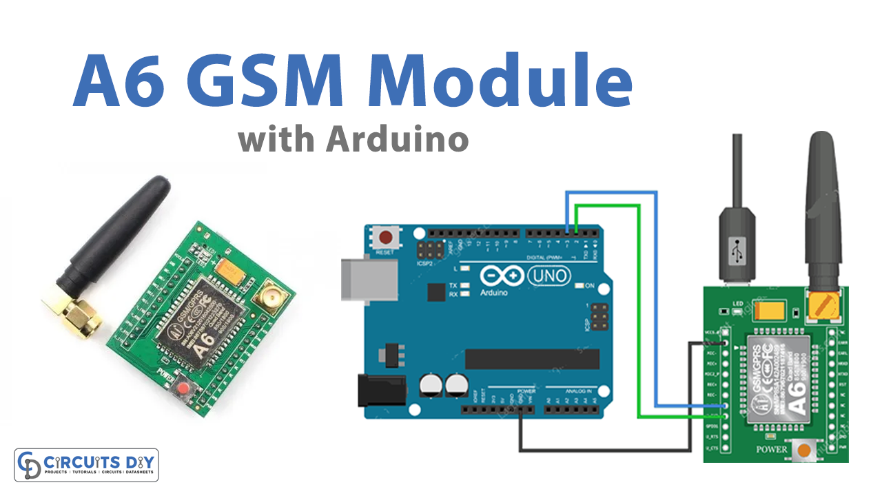
Circuit Diagram


Arduino Code
Testing AT Commands
#include <SoftwareSerial.h>

//Create software serial object to communicate with A6
SoftwareSerial mySerial(3, 2); //A6 Tx & Rx is connected to Arduino #3 & #2

void setup()
{
  //Begin serial communication with Arduino and Arduino IDE (Serial Monitor)
  Serial.begin(9600);

  //Begin serial communication with Arduino and A6
  mySerial.begin(9600);

  Serial.println("Initializing...");
  delay(1000);

  mySerial.println("AT"); //Once the handshake test is successful, it will back to OK
  updateSerial();
  mySerial.println("AT+CSQ"); //Signal quality test, value range is 0-31 , 31 is the best
  updateSerial();
  mySerial.println("AT+CCID"); //Read SIM information to confirm whether the SIM is plugged
  updateSerial();
  mySerial.println("AT+CREG?"); //Check whether it has registered in the network
  updateSerial();
}

void loop()
{
  updateSerial();
}

void updateSerial()
{
  delay(500);
  while (Serial.available())
  {
    mySerial.write(Serial.read());//Forward what Serial received to Software Serial Port
  }
  while(mySerial.available())
  {
    Serial.write(mySerial.read());//Forward what Software Serial received to Serial Port
  }
}
Arduino Code – Sending SMS
#include <SoftwareSerial.h>

//Create software serial object to communicate with A6
SoftwareSerial mySerial(3, 2); //A6 Tx & Rx is connected to Arduino #3 & #2

void setup()
{
  //Begin serial communication with Arduino and Arduino IDE (Serial Monitor)
  Serial.begin(9600);

  //Begin serial communication with Arduino and A6
  mySerial.begin(9600);

  Serial.println("Initializing...");
  delay(1000);

  mySerial.println("AT"); //Once the handshake test is successful, it will back to OK
  updateSerial();

  mySerial.println("AT+CMGF=1"); // Configuring TEXT mode
  updateSerial();
  mySerial.println("AT+CMGS=\"+ZZxxxxxxxxxx\"");//change ZZ with country code and xxxxxxxxxxx with phone number to sms
  updateSerial();
  mySerial.print("Last Minute Engineers | lastminuteengineers.com"); //text content
  updateSerial();
  mySerial.write(26);
}

void loop()
{
}

void updateSerial()
{
  delay(500);
  while (Serial.available())
  {
    mySerial.write(Serial.read());//Forward what Serial received to Software Serial Port
  }
  while(mySerial.available())
  {
    Serial.write(mySerial.read());//Forward what Software Serial received to Serial Port
  }
}
Reading SMS
#include <SoftwareSerial.h>

//Create software serial object to communicate with A6
SoftwareSerial mySerial(3, 2); //A6 Tx & Rx is connected to Arduino #3 & #2

void setup()
{
  //Begin serial communication with Arduino and Arduino IDE (Serial Monitor)
  Serial.begin(9600);

  //Begin serial communication with Arduino and A6
  mySerial.begin(9600);

  Serial.println("Initializing...");
  delay(1000);

  mySerial.println("AT"); //Once the handshake test is successful, it will back to OK
  updateSerial();

  mySerial.println("AT+CMGF=1"); // Configuring TEXT mode
  updateSerial();
  mySerial.println("AT+CNMI=1,2,0,0,0"); // Decides how newly arrived SMS messages should be handled
  updateSerial();
}

void loop()
{
  updateSerial();
}

void updateSerial()
{
  delay(500);
  while (Serial.available())
  {
    mySerial.write(Serial.read());//Forward what Serial received to Software Serial Port
  }
  while(mySerial.available())
  {
    Serial.write(mySerial.read());//Forward what Software Serial received to Serial Port
  }
}
Arduino Code – Making Call
#include <SoftwareSerial.h>

//Create software serial object to communicate with A6
SoftwareSerial mySerial(3, 2); //A6 Tx & Rx is connected to Arduino #3 & #2

void setup()
{
  //Begin serial communication with Arduino and Arduino IDE (Serial Monitor)
  Serial.begin(9600);

  //Begin serial communication with Arduino and A6
  mySerial.begin(9600);

  Serial.println("Initializing...");
  delay(1000);

  mySerial.println("AT"); //Once the handshake test is successful, i t will back to OK
  updateSerial();

  mySerial.println("ATD+ZZxxxxxxxxxx"); //  change ZZ with country code and xxxxxxxxxxx with phone number to dial
  updateSerial();
  delay(20000); // wait for 20 seconds...
  mySerial.println("ATH"); //hang up
  updateSerial();
}

void loop()
{
}

void updateSerial()
{
  delay(500);
  while (Serial.available())
  {
    mySerial.write(Serial.read());//Forward what Serial received to Software Serial Port
  }
  while(mySerial.available())
  {
    Serial.write(mySerial.read());//Forward what Software Serial received to Serial Port
  }
}
Arduino Code – Receiving Call
#include <SoftwareSerial.h>

//Create software serial object to communicate with A6
SoftwareSerial mySerial(3, 2); //A6 Tx & Rx is connected to Arduino #3 & #2

void setup()
{
  //Begin serial communication with Arduino and Arduino IDE (Serial Monitor)
  Serial.begin(9600);

  //Begin serial communication with Arduino and A6
  mySerial.begin(9600);

  Serial.println("Initializing...");
}

void loop()
{
  updateSerial();
}

void updateSerial()
{
  delay(500);
  while (Serial.available())
  {
    mySerial.write(Serial.read());//Forward what Serial received to Software Serial Port
  }
  while(mySerial.available())
  {
    Serial.write(mySerial.read());//Forward what Software Serial received to Serial Port
  }
}
Working Explanation
Connect A6 GSM Module & Arduino according to the circuit diagram. Now, for the initialization of commands use AT command code and upload the code in Arduino IDE. Now you will observe the initialization of the commands on the serial monitor. Write the sending SMS code and upload that too to send the message. To receive the message, write the receiving message code and upload it to your Arduino. To make a call, upload the code of making the call. And, to receive the call, write the code for receiving the code. Also, you can observe the readings on the Serial Monitor.
Code Explanation
TESTING AT COMMAND:
- First, include the SoftwareSerial.h library. Then Initialize the Arduino pins that are connected with the transmitter and the receiver pins.
- After that, in the void setup, Initialize serial monitor by Serial.begin( ). Initialize the link between the module and Arduino by using mySerial.begin( ). Then, create the basic connections to communicate with the GSM module. Send different commands by using mySerial. println( ). In the bracket write the some commands. For instance, use AT command to send some commands to query the module. In the same way, use AT+CSQ to test the signal quality. Similarly, to read the sim data use AT+CCID. Hence to check whether you are registered on the network, use AT+CREG?.
- In the void loop, call the function updateSerial( ) to wait for the coming input from the serial monitor and then send it to the module by the receiver pin (D2) of the module. Also, it read the transmitter pin (D3) continuously.
For SMS
FOR SENDING SMS:
- The code is essentially the same as the given code of AT command except for some snippets. There are some changes to be made in void setup. In the void setup, write mySerial.prinln(AT+CMGF=1) to choose the format of the message. Also, write mySerial.prinln(AT+CMGS=\”+ZZxxxxxxxxx\”) to transmit the SMS to this given phone number. Then use mySerial. Print( ) to send the text message to that number.
FOR RECIEVING SMS:
- The code is the same as the given code of AT command except for some snippets. Like in the void setup, use mySerial.prinln(AT+CMGF=1). Use mySerial. printin(“AT+CNMI=1,2,0,0,0”) to receive the message.
For Call
FOR MAKING CALL:
- Make some changes in the void setup of the above code. Use mySerial.prinln(“AT”) for the handshake. Now, use mySerial.prinln(AT+CMGS=\”+ZZxxxxxxxxx\”) to make a call on this phone number given in the bracket. Use mySerial.prinln(“ATH”) to hang up the call.
FOR RECIVING THE CALL:
- The code for receiving the call is very easy. It requires no extra effort. Same as the above code, except for the setup function. The setup function, only demands initializing the serial monitor.