In this tutorial, we are going to construct an exciting circuit. Generally, You can shield your car from destruction when cars are parked in the car park in reverse. It displays the distance from any object and warns when it hits the wall or the subject and must pause. This circuit is very convenient for the parking detector.
Hardware Component
The following components are required to make Reverse Car Parking Sensor Circuit
| S.no | Component | Value | Qty |
|---|---|---|---|
| 1. | Buzzer | – | 1 |
| 2. | Battery Connector | – | 1 |
| 3. | Battery | 9v | 1 |
| 4. | LED | – | 3 |
| 5. | IR Pair | – | 1 |
| 6. | Breadboard | – | 1 |
| 7. | Potentiometer | 10k | 3 |
| 8. | IC | LM358 | 2 |
| 9. | Resistor | 10k, 1k, 150 Ohm | 1, 3, 1 |
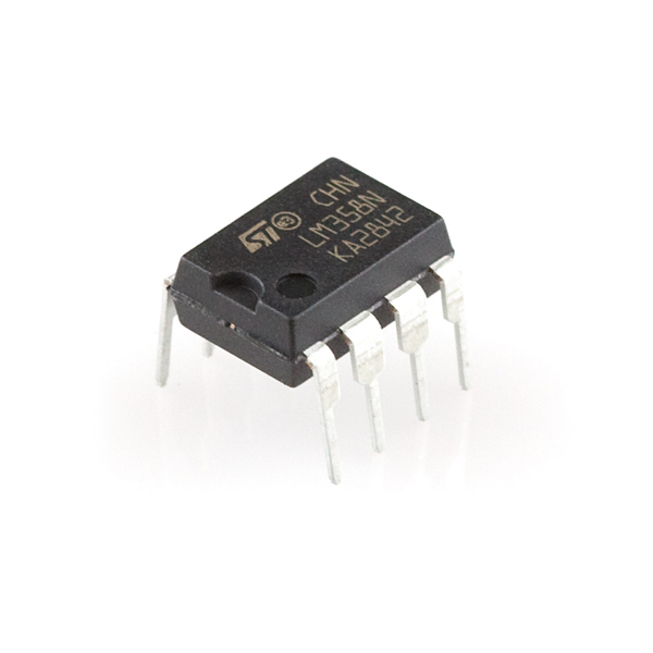
LM358 Pinout

For a detailed description of pinout, dimension features, and specifications download the datasheet of LM358
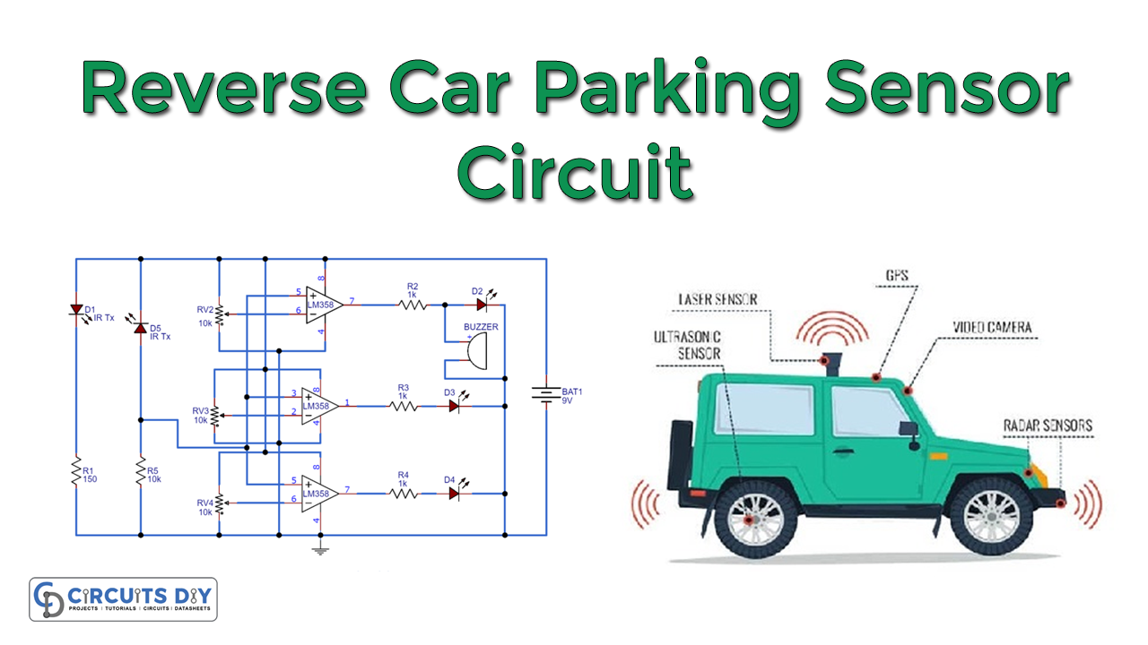
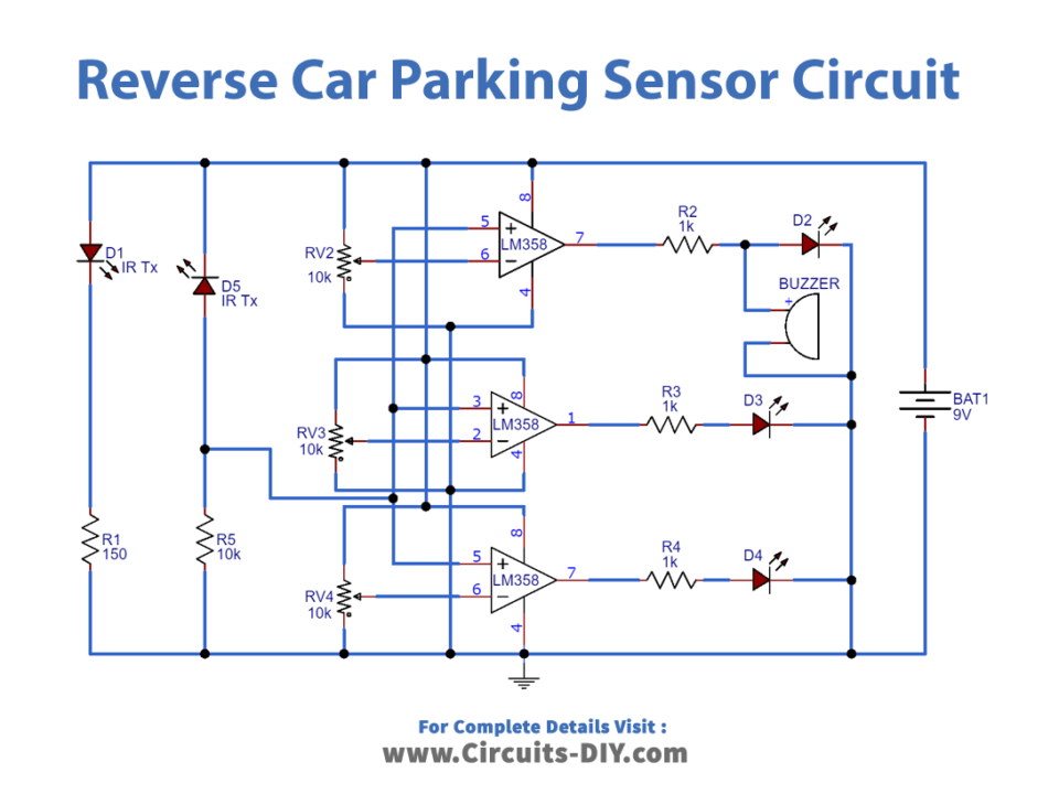
Reverse Car Parking Sensor Circuit
Working Explanation
We used an IR pair to detect the obstacles and two LM358 Double Variable resistor ICs to compare voltages in this car parking circuit. A container is linked to its inverting terminal to adjust the voltage level, and the IR receiver output is directly connected to all the comparators’ non-inverting pins. At the output of the LM358 U1:B IC, one Red Module is associated with the U2:A IC outlet pin (LM358), and one Green LED with the 1K resistor with the U2:B IC output pin (LM358). Red LED already has a buzzed
Applications and Uses
In this case, It’s challenging to determine the distance when parking your car if you are a new driver. This problem is solved by indicating the gap with three LED reverse parking sensor circuits. This device can be arranged easily on the back of the car


