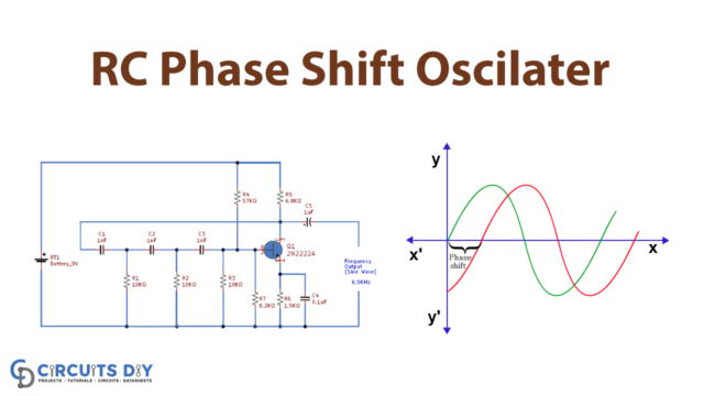
Introduction
To get the particular frequency and amplitude in numerous electronic circuits, oscillator circuits turn into a part of those circuits. Thus it shows a vital role in different microcontroller applications. There are also classifications in oscillators that include linear oscillators and non-linear oscillators, Hartley oscillators, Armstrong oscillators, negative resistance oscillators, Colpitts Oscillator circuits, etc. In this tutorial, we are going to the “RC phase shift oscillator Circuit”. But before making the circuit let us briefly discuss this type of oscillator.
What is RC Shift Oscillator?
RC shift is the linear oscillator that is used to provide the sin wave pulse. Thus, its circuit uses an operational amplifier or transistor. We can shift the phase of the amplifier to 1800 at the oscillation frequency by using a feedback network to provide a positive response. We frequently used these types of oscillators as audio oscillators.
Hardware Required
| S.no | Component | Value | Qty |
|---|---|---|---|
| 1. | NPN Transistor | 2N2222A | 1 |
| 2. | Capacitor | 1nF, 0.1μF, 1μF | 3,1,1 |
| 3. | Resistor | 57KΩ, 6.8KΩ, 1.5KΩ, 8.2KΩ, 10KΩ | 1,1,1,1,3 |
| 4. | Battery | 9V | 1 |
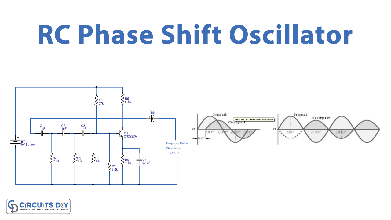
Circuit Diagram

Working Explanation
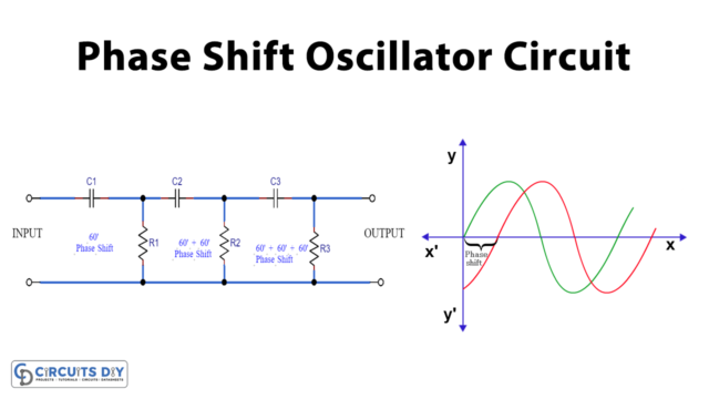
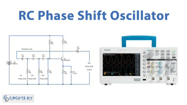
In this RC phase-shift Oscillator Circuit, 9V battery powers this whole RC phase-shift oscillator circuit. At first, we formed an RC network using the same value of capacitors and resistors. It means, that the oscillator feedback network comprises three stages of RC networks and these have exact values. Thus, each RC network provides 60 degrees phase shift. Since there are three networks, therefore, there is a total of 180 degrees phase shift.
Then we provide their output to the base of the transistor. This stage provides amplification with 180 degrees phase shift. And, as a result, there is 360 degrees phase shift in total. Here 2n222 transistor is wired as the common-emitter configuration. So, we take the output at the collector side of the transistor.
When we connect the supply to the circuit, there are random fluctuations in the base current, the transistor amplifies these fluctuations. RC phase-shift oscillator circuit provides stable low-frequency oscillation. We calculate the frequency by using the formula:
- Fr= 1/2π*RC*√2N
Where; N is the number of RC stages which in our case is 3. R and Care are the values of resistors and capacitors.
Application and Uses
- To generate signals of huge frequencies.
- Musical instruments.
- GPS units, etc