Overview
The integration of technology into everyday life continues to redefine how we interact with our surroundings. One such innovation is the development of weather detection systems that offer real-time information to enhance our preparedness for environmental changes. Rain detectors, in particular, play a crucial role in alerting individuals about impending rainfall, allowing them to take necessary precautions
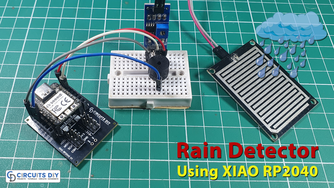
In today’s tutorial, we are going to make a “Rain Detector & Alarm System” using the XIAO RP2040 Microcontroller.
Understanding the XIAO RP2040
The XIAO RP2040, powered by the Raspberry Pi RP2040 microcontroller chip, is a compact and versatile development board known for its efficiency and flexibility in various projects. With its small size and impressive capabilities, it serves as an excellent platform for crafting innovative solutions.

PCBGOGO has offered high-quality PCBs and the best PCB assembly service all over the world since 2015. Discover an incredible offer that puts PCB prototyping within reach for just $1. Yes, you read that right – for only a dollar, you can bring your innovative ideas to life with a PCB prototype. Don’t miss out on this fantastic opportunity to turn your electronics projects into reality. Explore the campaign here: PCBGOGO $1 PCB Prototype and pave the way for your next big creation!
Hardware Components
You’ll need the following hardware components to get started:
| Components | Value / Model | Qty |
|---|---|---|
| PCB | PCB-GOGO | |
| XIAO | RP2040 | 1 |
| Rain Sensor | – | 1 |
| Buzzer | – | 1 |
| Jumper Wires | – | 1 |
XIAO RP2040 Pinout

For details on the datasheet of the XIAO RP2040 Microcontroller visit this link.
| Pin No | Pin Name |
|---|---|
| 1 | P26 / A0 / D0 |
| 2 | P27 / A1 / D1 |
| 3 | P28 / A2 / D2 |
| 4 | P29 / A3 / D3 |
| 5 | P6 / SDA/ D4 |
| 6 | P7 / SCL / D5 |
| 7 | P0 / TX / D6 |
| 8 | P1 / RX / CSN / D7 |
| 9 | P2 / SCK / D8 |
| 10 | P3 / MISO / D9 |
| 11 | P4 / MOSI / D10 |
| 12 | 3V3 |
| 13 | GND |
| 14 | 5V |
Rain Sensor Pinout

| Pin No | Pin Name | Pin Description |
|---|---|---|
| 1 | VCC | VCC is the +5 volt Positive Pin |
| 2 | GND | GND is the (Ground) Negative |
| 3 | D0 | Digital Output |
| 4 | A0 | Analog Output |
Steps-by-Step Guide
(1) Setting up Arduino IDE
Download Arduino IDE Software from its official site. Here is a step-by-step guide on “How to install Arduino IDE“.
(2) XIAO RP2040 in Arduino IDE
There’s an add-on that allows you to program the XIAO RP2040 using the Arduino IDE. Here is a step-by-step guide on “How to Install XIAO RP2040 on Arduino IDE“.
(3) Schematic
Make connections according to the circuit diagram given below.
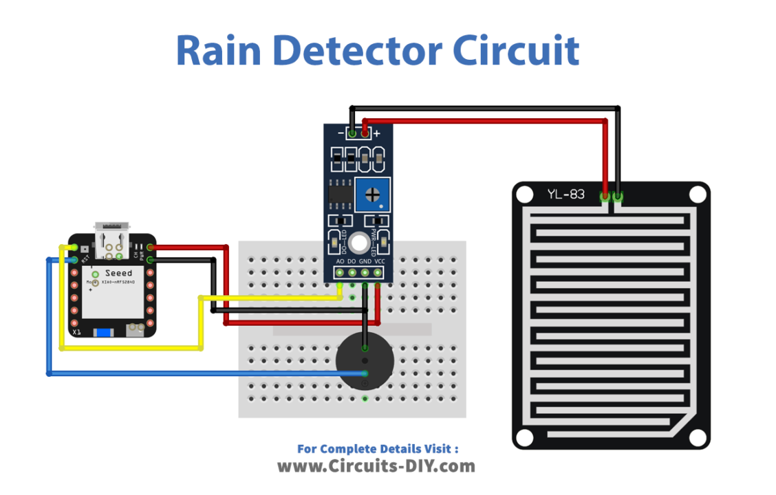
Wiring / Connections
| XIAO RP2040 | Rain Sensor | Buzzer |
|---|---|---|
| 5V | VCC | |
| GND | GND | GND |
| D0 | AO | – |
| D2 | – | +ve |
(4) Uploading Code
Now copy the following code and upload it to Arduino IDE Software.
// Circuits DIY
// For Complete Details Visit -> https://www.circuits-diy.com/rain-detector-and-alarm-system-using-xiao-rp2040

int Rain_Sensor = D0;
int Buzzer = D2;

void setup() {
  Serial.begin(9600);//Enable serial monitor
  pinMode(Rain_Sensor, OUTPUT); //Define Rain Sensor
  pinMode(Buzzer, OUTPUT); //Define Buzzer for rain indication
}
void loop()
{
  int value = analogRead(Rain_Sensor); //Read Sensor Value
  Serial.print("Value : ");
  Serial.println(value);

  if (value < 300) { //Set Value accoring to sensor calibration
    digitalWrite(Buzzer, HIGH);
    Serial.print("It's Raining Outside");
    delay(2000);
  } else {
    digitalWrite(Buzzer, LOW);
  }
}
How code works
This code is designed for a Rain Detector and Alarm System using the XIAO RP2040 microcontroller. Here’s a brief explanation of the code:
int Rain_Sensor = D0;andint Buzzer = D2;: These lines declare the pins connected to the rain sensor and buzzer, respectively.void setup(): This function is called once when the microcontroller starts. It initializes the serial communication for debugging and sets the pin modes for the rain sensor and buzzer as OUTPUT.void loop(): This function runs repeatedly as long as the microcontroller is powered. It reads the analog value from the rain sensor, prints it to the serial monitor, and checks whether it’s raining based on the sensor reading.int value = analogRead(Rain_Sensor);: Reads the analog value from the rain sensor connected to pin D0 and stores it in the variablevalue.if (value < 300) {: Checks if the sensor value is less than 300 (which might be the calibrated threshold for detecting rain). If it’s less, it considers it as rain and turns on the buzzer by setting the pin D2 (connected to the buzzer) to HIGH, indicating rainfall. It also prints “It’s Raining Outside” to the serial monitor and adds a delay of 2000 milliseconds (2 seconds) before checking the sensor value again.else { digitalWrite(Buzzer, LOW); }: If the sensor value is not less than 300, it turns off the buzzer by setting the pin D2 to LOW, indicating that it’s not raining.
Conclusion
The rain Detector and Alarm System utilizing the XIAO RP2040 microcontroller represents a significant stride in leveraging technology for weather awareness and safety. This innovative system, powered by the capabilities of the XIAO RP2040 and a rain sensor, offers a practical solution for detecting rainfall and triggering alerts in real time.


