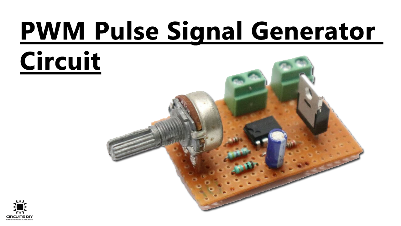
What is a PWM Pulse Signal Generator?
Pulse width modulation or PWM governs the transfer of power from one electrical/electronic component to another. Basically, in pulse width modulation, the energy is divided between a series of pulses, rather than a continuously varying analog signal. A PWM Pulse Signal Generator implements the PWM function, using which you can control devices such as DC motors. So, In today’s tutorial, we are going to design a simple PWM Pulse Signal Generator Circuit Using LM358 Op-Amp IC.
The main component of this circuit is an LM358 IC. LM358 is a dual op-amp IC integrated with two op-amps powered by a common power supply. It can be considered as one-half of the LM324 Quad op-amp which contains four op-amps with a common power supply.
JLCPCB is the foremost PCB prototype & manufacturing company in china, providing us with the best service we have ever experienced regarding (Quality, Price Service & Time).
Hardware Required
The following components are required to make Pulse Signal Generator Circuit
| S. no | Component | Value | Qty |
|---|---|---|---|
| 1. | Op-Amp IC | LM358 | 1 |
| 2. | DC Motor | 9V, 12V/6000 – 10000RPM | 1 |
| 3. | Power MOSFET | IRF540 | 1 |
| 4. | Potentiometer | 10K | 1 |
| 5. | Capacitor | 0.1uF | 1 |
| 6. | Resistor | 47K, 10K, 1K | 3 |
| 7. | Soldering Iron | 45W – 65W | 1 |
| 8. | Soldering Wire with Flux | – | 1 |
| 9. | Terminal Block Connectors | – | 1 |
| 10. | DC Battery | 9V/12V | 1 |
| 11. | Battery Clips | – | 1 |
| 12. | Veroboard | – | 1 |
| 13. | Jumper Wires | – | As per need |
LM358 Pinout

For a detailed description of pinout, dimension features, and specifications download the datasheet of LM358
IRF540 Pinout
For a detailed description of pinout, dimension features, and specifications download the datasheet of IRF540
Useful Steps
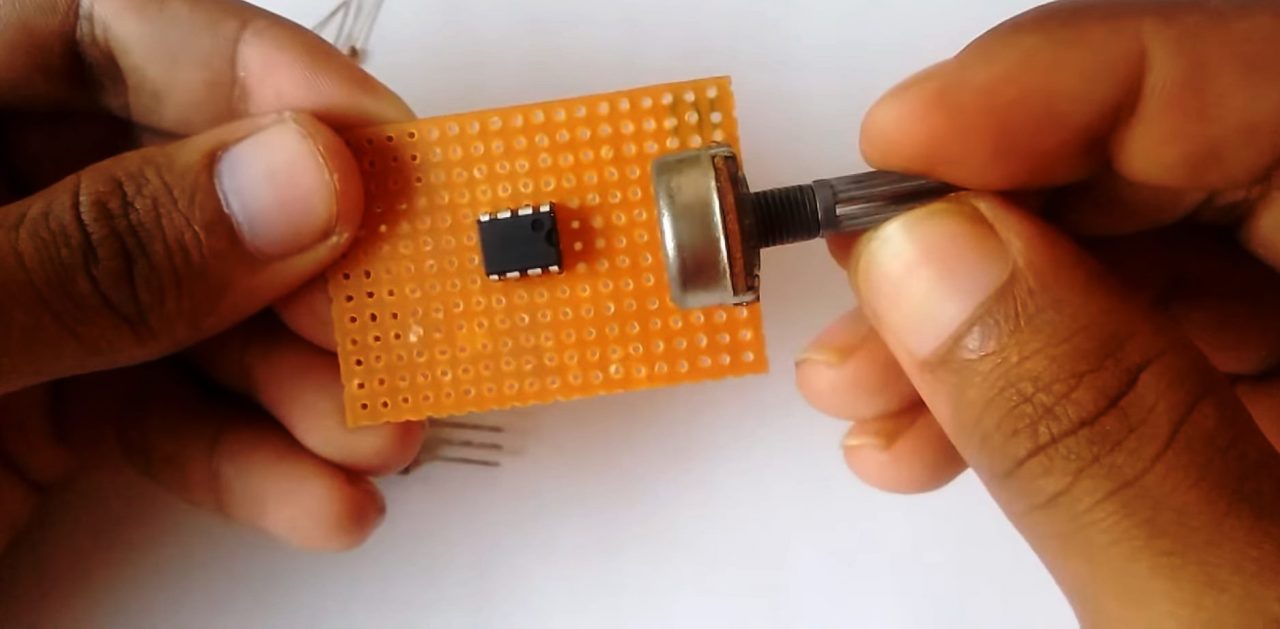
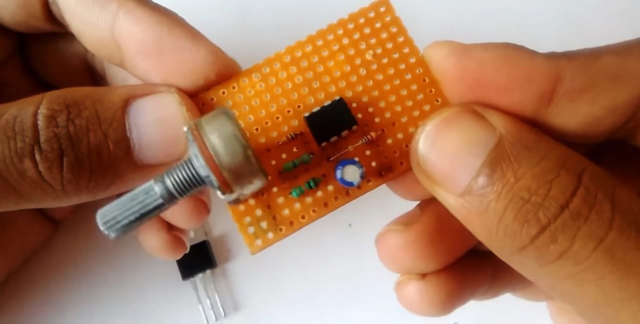
1) Solder the LM358 IC on the Veroboard. After that, Solder the fixed ends of the 10K pot with the GND & VCC of the IC.
2) Solder a 1K resistor between the variable end of the 10K pot & pin 3 of the IC. After that, Solder the +ve terminal of the 0.1uF capacitor with pin 2 & -ve terminal to pin 4 of the IC.
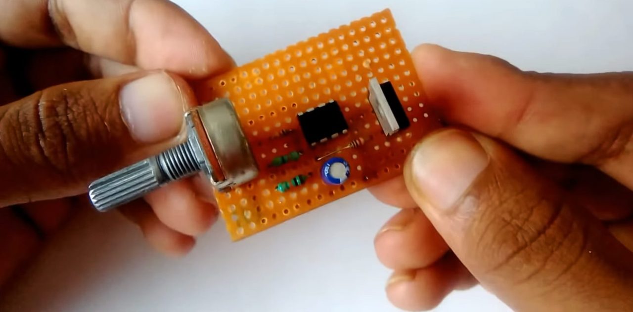
3) Now, Solder a 1K resistor between the gate terminal of IRF540 MOSFET & pin 1 of the IC. After that, solder a 10K resistor between pins 1 & 2 of the IC.
4) Solder a 47K resistor between Pin 1 & 3 of the IC.
5) Solder the source terminal of the IRF540 with pin 4 of the IC.
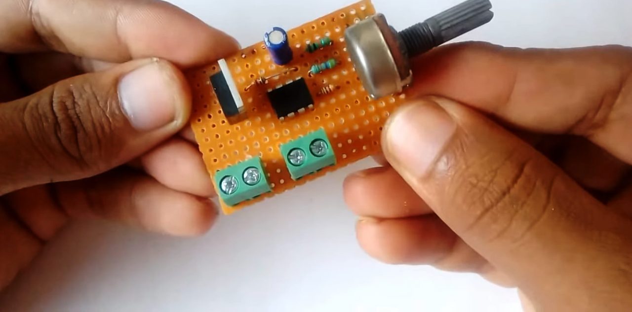
6) Solder the I/O Terminal block connectors on the Veroboard.
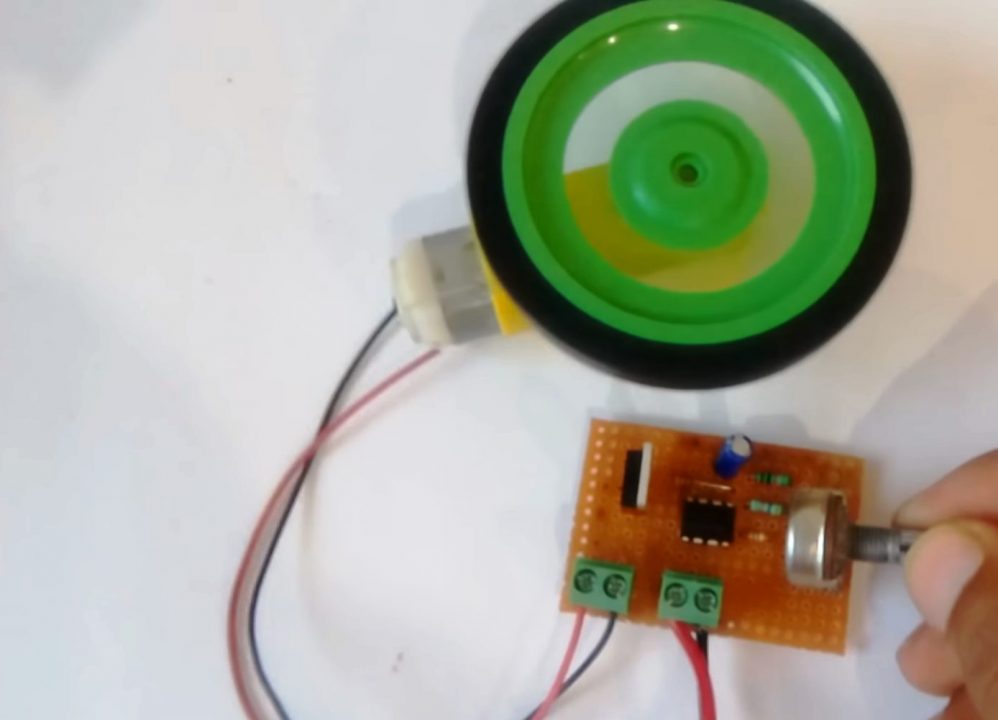
7) Connect a DC motor or an LED to the circuit output, in order to adjust the duty cycle of the PWM signal. Now, Power up & test the circuit.
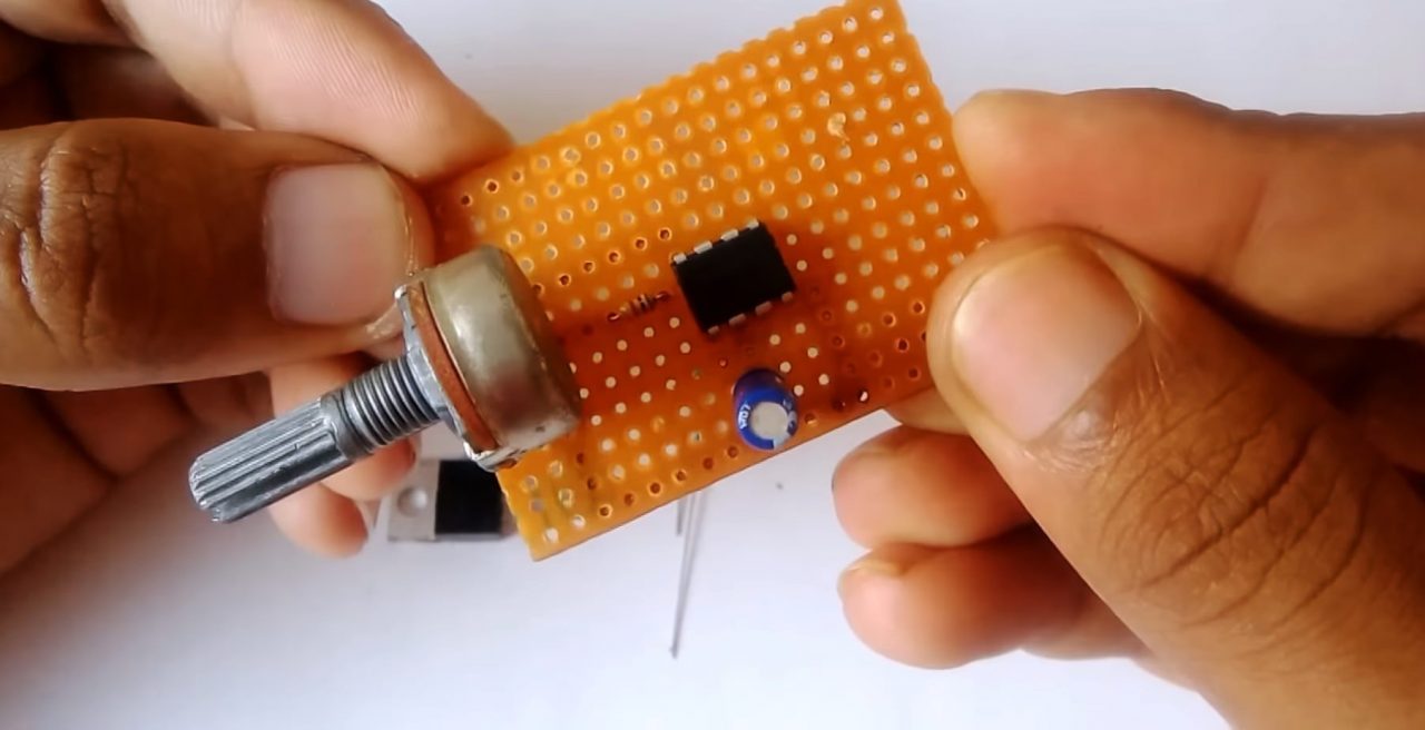
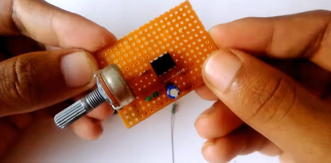
Pulse Signal Generator Circuit
Working Explanation
The working of the circuit is as follows: Here we are using an LM358 Op-Amp in A-stable multi-vibrator mode to produce a free-running square wave signal. Here, an RC circuit is connected across the output Pin no. 3 of the LM358 op-amp. So that the charging/discharging of the 0.1uF capacitor can be used to create a free-running square signal continuously. You can adjust the duty cycle(%) of the PWM square signal using the 10K preset pot.
The RC square wave output of the Op-Amp IC serves as the control signal to the gate terminal of the IRF540 power MOSFET. The drain output of which is connected to a DC motor, allowing it to be driven at a high current.
Applications
- PWM signal is used for applications such as controlling DC motors, valves, pumps, hydraulics, and other mechanical parts.
- Computer Motherboards require PWM Signals that control the heat generated on the board.