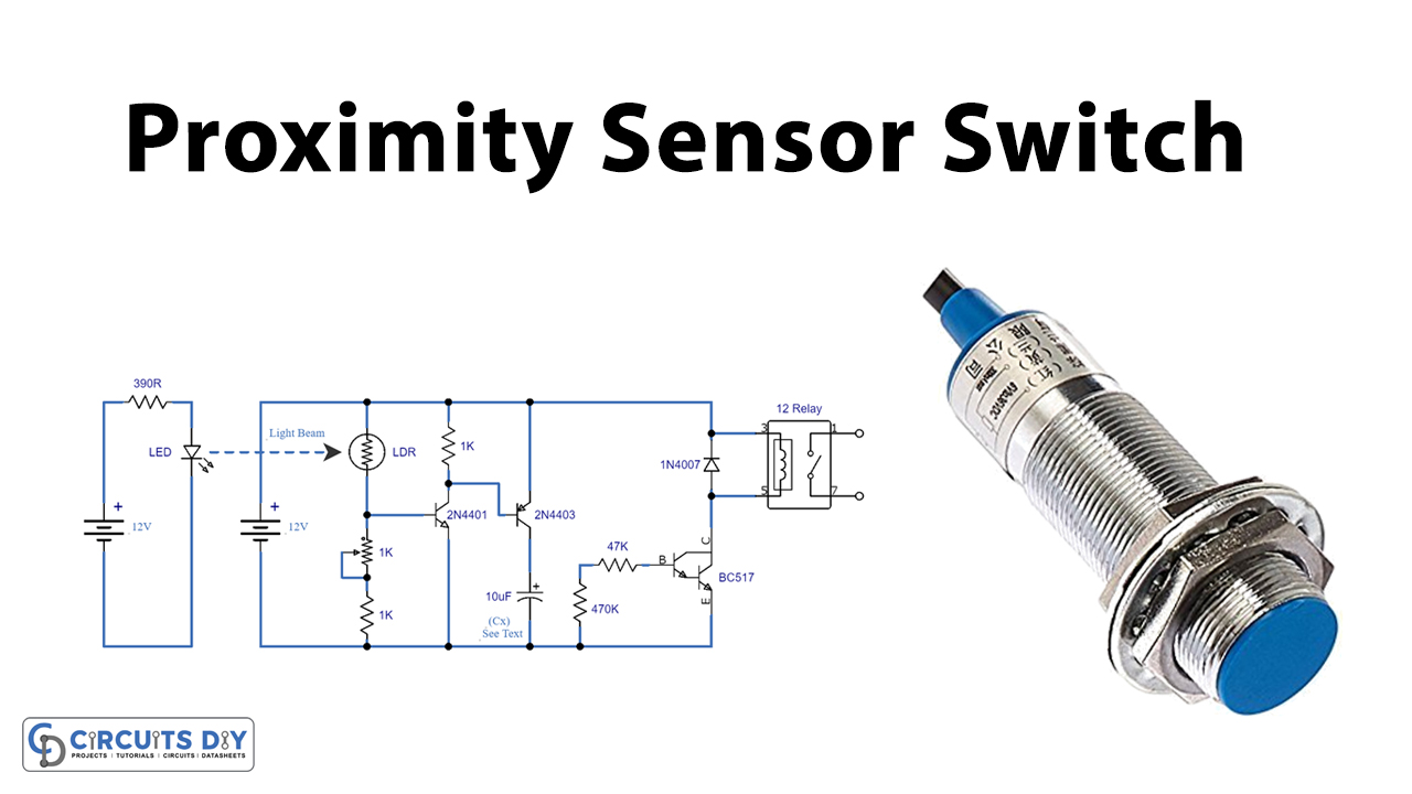
The proximity sensor switch works such that there is a blockage due to a person or object in between the circuit. the circuit contains an LDR, transistors, and relay as main components. The relay can be connected to any external circuitry to turn it ON for a set amount of time.

Hardware Components
The following components are required to make Proximity Sensor Switch Circuit
| S.no | Component | Value | Qty |
|---|---|---|---|
| 1. | Transistor | 2N4401 | 1 |
| 2. | Transistor | BC517 | 1 |
| 3. | LDR | – | 1 |
| 4. | Diode | 1N4007 | 1 |
| 5. | Relay | 12V | 1 |
| 6. | LED | – | 1 |
| 7. | Battery | 12V | 1 |
| 8. | Variable resistor | 1KΩ | 1 |
| 9. | Resistors | 390Ω, 1KΩ, 47KΩ, 470KΩ | 1,2,1,1 |
| 10. | Electrolytic capacitor | 10µF | 1 |
BC517 Pinout
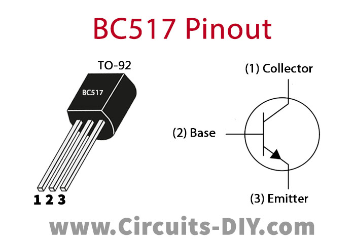
For a detailed description of pinout, dimension features, and specifications download the datasheet of BC517
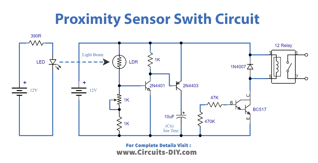
Proximity Sensor Switch Circuit
Working Explanation
The circuit contains three parts; the first one is the bright LED circuit, the second one has an LDR connected with two transistors and the third one is the relay switch operated through the Darlington pair transistor.
In order to set the circuit up, place the LED at a distance of 5-10m from the placement of LDR. The distance is such that LDR keeps on receiving light from the LED. As the LDR principle goes, when light strikes the LDR it will turn OFF the circuit connected to it. Hence, as long as there is no blockage between LED and LDR, the circuit containing the relay switch remains in the OFF state. Adjust the sensitivity of the circuit using a 1KΩ variable resistor.
When a blockage is it a person or an object comes in between LED and LDR, the LDR passes through the electrical current. This electrical signal is received by the two transistors 2N4401 where it is amplified. This amplified signal, thus, goes through the electrolytic capacitor of 10µF whose value is set such that the relay ON time is adjusted. Further increasing the value of the capacitor say 1000µF and 2200µF the relay switch ON time can be increased to 5 min and 10 min, respectively.
The Darlington pair does both the amplification of current and the switching of relay. Thereby, activating the relay switch. The relay switch remains ON until the set time.
Application
- Automation system of a house


