Introduction
Welcome to the world of DIY electronics! Are you tired of the boring, generic doorbells that do nothing more than make a generic chime? Look no further because, in this blog post, we’re going to show you how to build your very own programmable electronic doorbell circuit. Even if you’re a beginner, with a little guidance, you’ll be well on your way to building your own one-of-a-kind doorbell. So, grab your components, and let’s start creating the ultimate doorbell upgrade!
In this blog post, we’ll take you step by step through building your programmable electronic doorbell circuit. We’ll cover everything from selecting the right components to making the connections. We’ll also provide detailed instructions and helpful tips to ensure a smooth building experience. By the end of this project, not only will you have a truly unique doorbell, but you’ll also have the satisfaction of knowing that you built it yourself. Let’s get started!
Hardware Required
You will require the following hardware for the Programmable electronic Door Bell Circuit.
| S.no | Component | Value | Qty |
|---|---|---|---|
| 1. | IC | SAE800 | 1 |
| 2. | Transformer | – | 1 |
| 3. | Polar Capacitor | – | 2 |
| 4. | Non-Polar Capacitor | – | 3 |
| 5. | Variable Resistor | – | 1 |
| 6. | Resistor | – | 5 |
| 7. | Diode | – | 4 |
| 8. | Speaker | – | 1 |
| 9. | Jumper wire | – | 1 |
Circuit Diagram

Testing
To test the programmable electronic doorbell music circuit, follow these steps:
- Connect the circuit to a power source.
- Press the bell switch to activate the internal logic and produce the first tone.
- Adjust the trimmer R6 to set the desired sound level.
- Use buttons 1, 2, and 3 to switch between the different modes of operation (monotonic, bitonal, and tritonal).
- Observe the speaker and listen to the different tones to ensure they are being produced correctly.
- Check the circuit’s power consumption to ensure that it is operating efficiently.
- If the circuit is not working as expected, check all connections and components for proper placement and continuity.
- Repeat the above steps with different sound settings to ensure that the circuit is fully functional and programmable.
Working Explanation
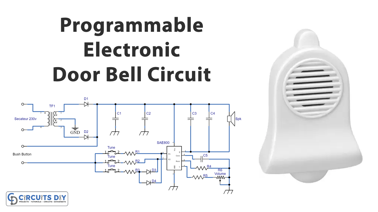
This circuit is a programmable electronic doorbell music circuit that uses a 230V mains power supply. The power supply is extracted from the mains by a transformer, TF1, which has a secondary of 2x9V with a central tap. This is then rectified by diodes D1 and D2, which create a full-wave rectification, meaning that both half-waves are rectified. The middle connection is grounded, and when the polarity of the low-voltage sinusoid is at its maximum positive level, D1 conducts, and D2 is blocked. In the reverse situation, D1 is blocked, and D2 conducts. This results in pulses of sinusoidal waves at 100 Hz at the terminals of capacitors C1 and C2, which are then loaded to a consistent potential of approximately 11 volts. This is enough to operate the integrated circuit.
The integrated circuit is connected to a speaker with an impedance of 8 ohms. The speaker’s positive terminal is connected to the positive power supply. There are also capacitors in parallel, whose function is to clip the level transitions in order to make the small speaker reproduce smooth and enlightening tones. The level is easily adjustable with the trimmer R6. The trimmer works in conjunction with R5 to adjust the current in the speaker, which in turn affects the output level of the amplifier stage.
The SAE800 circuit is in a dormant state and consumes only a few microamperes of power when there is no sound. To produce sound, one must press the bell switch attached to the push button terminals, activating the internal logic and producing the first tone. Depending on the setting of the jumpers, this may be followed by a second and third tone. To set the desired sound, one must apply a high logic voltage (5 V) to the applied voltage pin 3 and one of the control pins (7 or 8). If these pins are open or connected to the ground, the circuit is in “standby” mode and consumes very little power.
The circuit has three different modes of operation: monotonic, bitonal, and tritonal. To switch between these modes, one must adjust jumpers 1, 2, and 3. When jumper 1 is closed, the circuit is in monotonic mode, producing a single note that diminishes steadily. When jumper 2 is closed, the circuit is in bitonal mode and produces a sequence of two-shifted, dissolved, and damping audio. Finally, when jumper 3 is closed, the circuit is in tritonal mode, and a diode array (D3 and D4) provides the high logic level and switches to the three-tone mode in a shifted diminishing sequence.
The IC in this circuit is activated with a specific delay according to the activation of the input to prevent unnecessary and harmful commutation for the circuit’s proper functioning. R4 and C5 have values that are decided to run the oscillator at a frequency of approximately 28.4 kHz, where the 3 notes are subsequently drawn: the first note is high, the second is medium, and the third is low.
Final Words
In conclusion, building a Programmable electronic Door Bell Circuit can be a fun and rewarding experience. Anyone can create this circuit with little knowledge and the right tools. Always follow proper safety guidelines, double-check your connections, and troubleshoot any issues that may arise. If you have any questions or concerns, please feel free to ask in the comments section, and we will be happy to assist you. Happy building!

