A power failure alarm circuit is a very useful circuit that helps in diagnosing the cut-off or absence of the main power supply during any experimental setup or in some power critical instruments just like life care devices installed in hospitals. When the power supply cuts off circuit will turn the alarm on along with the glow of a white bright LED.
Hardware Required
| S.no | Component | Value | Qty |
|---|---|---|---|
| 1. | Transformer | 100-500mA | 1 |
| 2. | Resistor | 1K, 220 ohm | 1, 1 |
| 3. | Diode | 1N4007 | 4 |
| 4. | LED | – | 2 |
| 5. | Speaker | 8 ohm | 1 |
| 6. | Capacitor | 1000uF | 1 |
| 7. | NPN Transistor | 2N3904 | 1 |
| 8. | Relay | 12V | 1 |
| 9. | Switch | – | 1 |
| 10. | IC | UM66 | 1 |
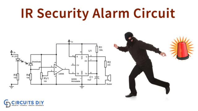
Circuit Diagram

Working Explanation:
The working of this power failure alarm circuit is very simple. A power Supply of 220 volts is turned on. This 220 volt is converted into 12 volts by the step-down transformer. Rectification is done by a diode bridge. The diode bridge consists of 4 diodes connected in series with each other. The rectified 12 volts are then supplied to the relay which is in on condition when the main supply is active. When the main supply is cut off relay is turned off and a 3-volt batter voltage is supplied to the alarm and LED which shows the absence of the main power supply.