Introduction
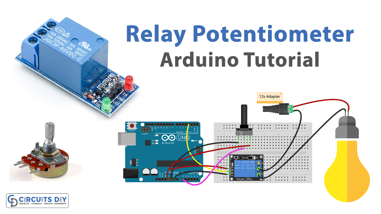
A potentiometer analog threshold-controlled 5V SPDT relay module is a system that uses a potentiometer as an input device to control the state of a Single Pole Double Throw (SPDT) relay module. The potentiometer is connected to an analog pin of an Arduino microcontroller, which reads the voltage level of the potentiometer and converts it to a digital value using the built-in Analog-to-Digital Converter (ADC). The Arduino then compares this value to a threshold value, which is set in the code, and uses it to control the state of the relay module.
The relay module is a device that allows the microcontroller to switch the state of an external load, such as an LED or a motor, by switching the state of an internal switch. The SPDT relay has 3 pins, one common pin, and two normally open and normally closed pins. By switching the state of the relay, the common pin is connected to one of the other two pins, this allows for a change in the state of the load connected to it.
Hardware Components
You will require the following hardware for Potentiometer Triggers Relay with Arduino.
| S.no | Component | Value | Qty |
|---|---|---|---|
| 1. | Arduino UNO | – | 1 |
| 2. | USB Cable Type A to B | – | 1 |
| 3. | Potentiometer | – | 1 |
| 4. | Relay | – | 1 |
| 5. | Warning Light Bright Waterproof | – | 1 |
| 6. | DC Power Jack | – | 1 |
| 7. | Power Adapter for Arduino | 9V | 1 |
| 8. | Power Adapter | 12V | 1 |
| 9. | Jumper Wires | – | 1 |
Potentiometer Triggers Relay with Arduino
- Connect the potentiometer to the analog pin of the Arduino, such as A0.
- Connect the SPDT relay module to the digital pin of the Arduino, such as D8.
- Connect the relay’s Common pin to the load you want to control, such as an LED or a motor.
- In the Arduino IDE, open a new sketch and include the following library at the beginning of the sketch:
#include <Arduino.h> - In the setup() function, initialize the serial communication using the Serial.begin() function and set the baud rate. Also, set the pin mode of the relay pin as OUTPUT. For example:
void setup() {
  Serial.begin(9600);
  pinMode(8, OUTPUT);
}
- In the loop() function, read the analog value from the potentiometer using the analogRead() function and store it in a variable. For example:
void loop() {
  int sensorValue = analogRead(A0);
- Set a threshold value for the potentiometer, for example, if the potentiometer is greater than 512, turn on the relay and if it is less than 512, turn off the relay.
if (sensorValue > 512) {
    digitalWrite(8, HIGH); // turn on relay
    Serial.println("Relay ON");
  } else {
    digitalWrite(8, LOW); // turn off relay
    Serial.println("Relay OFF");
  }
- Add a delay() function to control the rate of updates. For example:
delay(100);- Add a variable to store the relay state and print the state on the serial monitor.
String relayState = "OFF";
  if (digitalRead(8) == HIGH) relayState = "ON";
  Serial.print("Relay state: ");
  Serial.println(relayState);
- Upload the code to the Arduino board and open the serial monitor to view the status of the relay and the potentiometer value.
Schematic
Make connections according to the circuit diagram given below.

Installing Arduino IDE
First, you need to install Arduino IDE Software from its official website Arduino. Here is a simple step-by-step guide on “How to install Arduino IDE“.
Installing Libraries
Before you start uploading a code, download and unzip the following libraries at /Progam Files(x86)/Arduino/Libraries (default), in order to use the sensor with the Arduino board. Here is a simple step-by-step guide on “How to Add Libraries in Arduino IDE“.
Code
Now copy the following code and upload it to Arduino IDE Software.
Arduino Code – Analog Threshold
const int POTENTIOMETER_PIN = A0; // Arduino pin connected to Potentiometer pin
const int RELAY_PIN         = 3;  // Arduino pin connected to Relay's pin
const int ANALOG_THRESHOLD  = 500;

void setup() {
  pinMode(RELAY_PIN, OUTPUT); // set arduino pin to output mode
}

void loop() {
  int analogValue = analogRead(POTENTIOMETER_PIN); // read the input on analog pin

  if(analogValue > ANALOG_THRESHOLD)
    digitalWrite(RELAY_PIN, HIGH); // turn on Relay
  else
    digitalWrite(RELAY_PIN, LOW);  // turn off Relay
}
Arduino Code – Voltage Threshold
const int POTENTIOMETER_PIN   = A0; // Arduino pin connected to Potentiometer pin
const int RELAY_PIN           = 3; // Arduino pin connected to Relay's pin
const float VOLTAGE_THRESHOLD = 2.5; // Voltages

void setup() {
  pinMode(RELAY_PIN, OUTPUT); // set arduino pin to output mode
}

void loop() {
  int analogValue = analogRead(POTENTIOMETER_PIN);      // read the input on analog pin
  float voltage = floatMap(analogValue, 0, 1023, 0, 5); // Rescale to potentiometer's voltage

  if(voltage > VOLTAGE_THRESHOLD)
    digitalWrite(RELAY_PIN, HIGH); // turn on Relay
  else
    digitalWrite(RELAY_PIN, LOW);  // turn off Relay
}

float floatMap(float x, float in_min, float in_max, float out_min, float out_max) {
  return (x - in_min) * (out_max - out_min) / (in_max - in_min) + out_min;
}
Working Explanation
The process starts by connecting the potentiometer to the analog pin of the Arduino, such as A0, and connecting the SPDT relay module to a digital pin of the Arduino, such as D8. The relay’s common pin is connected to the load you want to control, such as an LED or a motor.
In the setup() function, the serial communication is initialized using the Serial.begin() function, and the baud rate is set. Also, the pin mode of the relay pin is set as OUTPUT. In the loop() function, the analog value from the potentiometer is read using the analogRead() function and stored in a variable. Then, a threshold value for the potentiometer is set. If the potentiometer value is greater than the threshold, the relay is turned on and if it is less than the threshold, the relay is turned off. The state of the relay is then read using digitalRead() and stored in a variable. The state of the relay is then printed on the serial monitor along with the potentiometer value.
Applications
- DIY projects
- Monitoring and control of electrical systems
- Audio and video equipment
- Medical devices
- Environmental monitoring
- Agriculture
- Automotive
- Energy management
- Gaming
Conclusion
We hope you have found this Circuit very useful. If you feel any difficulty in making it feel free to ask anything in the comment section.


