Introduction
A potentiometer’s analog threshold-dependent LED switch is a circuit that uses a potentiometer (a type of variable resistor) to control the brightness of an LED. The LED is connected to an Arduino microcontroller, which reads the value of the potentiometer and compares it to a predefined threshold value.
This type of circuit is often used to demonstrate the capabilities of the Arduino UNO board and to provide a simple example of using analog inputs and digital outputs with the microcontroller. It can also be used as a building block for more complex projects that require analog input/output control.
Hardware Components
You will require the following hardware for Potentiometer Triggers LED
| S.no | Component | Value | Qty |
|---|---|---|---|
| 1. | Arduino UNO | – | 1 |
| 2. | USB Cable Type A to B | – | 1 |
| 3. | Potentiometer | – | 1 |
| 4. | Power Adapter for Arduino | 9V | 1 |
| 5. | LED | – | 1 |
| 6. | Resistor | 220Ω | 1 |
| 7. | Breadboard | – | 1 |
| 8. | Jumper Wires | – | 1 |
Potentiometer Triggers LED
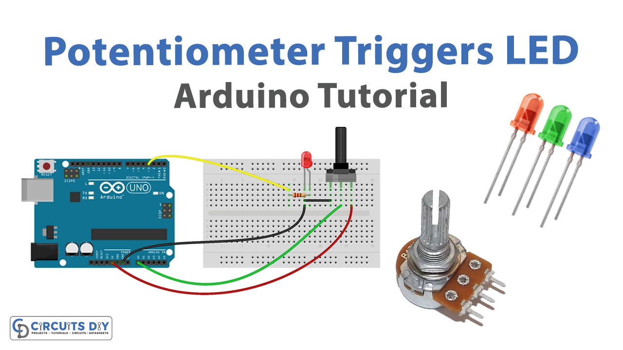
- Connect the LED to the breadboard. Connect the shorter leg of the LED to a row on the breadboard, and the longer leg to a different row. If you are using a 220-ohm resistor, connect it between the LED and the breadboard row as well.
- Connect the potentiometer to the breadboard. Connect one end of the potentiometer to a row on the breadboard and the other two ends to different rows.
- Connect the breadboard to the Arduino. Connect one end of a jumper wire to the row with the shorter leg of the LED and the other end to a digital output pin (e.g. D8) on the Arduino. Connect another jumper wire from the row with the longer leg of the LED to a ground pin on the Arduino. Connect one end of a jumper wire to one of the rows of the potentiometer and the other end to an analog input pin (e.g. A0) on the Arduino. Connect another jumper wire from the other row of the potentiometer to a power supply pin (e.g. 5V) on the Arduino.
- Open the Arduino software on your computer and create a new sketch by clicking “File” and then “New.”
- Declare a global variable to hold the analog threshold value that will trigger the LED. This value will be set in the setup function and used in the loop function to determine when to turn the LED on and off.
- In the setup function, set the pin mode for the digital output pin that the LED is connected to by adding the following line of code at the beginning of the sketch:
pinMode(8, OUTPUT);Replace “8” with the actual pin number of the digital output pin that the LED is connected to (e.g. D8 corresponds to pin 8).
- In the setup function, set the analog threshold value by reading the initial value of the potentiometer using the analogRead function and storing it in the global variable. Add the following lines of code to do this:
int threshold = analogRead(0);Replace “0” with the actual pin number of the analog input pin that the potentiometer is connected to (e.g. A0 corresponds to pin 0).
- In the loop function, read the current value of the potentiometer using the analogRead function and compare it to the analog threshold value. Add the following lines of code to do this:
int potValue = analogRead(0);
if (potValue >= threshold) {
digitalWrite(8, HIGH);
} else {
digitalWrite(8, LOW);
}
Replace “0” and “8” with the actual pin numbers of the analog input and digital output pins that the potentiometer and LED are connected to (e.g. A0 corresponds to pin 0 and D8 corresponds to pin 8).
- Upload the sketch to the Arduino and test the LED behavior by turning the potentiometer.
Schematic
Make connections according to the circuit diagram given below.

Installing Arduino IDE
First, you need to install Arduino IDE Software from its official website Arduino. Here is a simple step-by-step guide on “How to install Arduino IDE“.
Code
Now copy the following code and upload it to Arduino IDE Software.
Arduino Code – Analog Threshold
const int POTENTIOMETER_PIN = A0; // Arduino pin connected to Potentiometer pin
const int LED_PIN           = 3;  // Arduino pin connected to LED's pin
const int ANALOG_THRESHOLD  = 500;

void setup() {
  pinMode(LED_PIN, OUTPUT); // set arduino pin to output mode
}

void loop() {
  int analogValue = analogRead(POTENTIOMETER_PIN); // read the input on analog pin

  if(analogValue > ANALOG_THRESHOLD)
    digitalWrite(LED_PIN, HIGH); // turn on LED
  else
    digitalWrite(LED_PIN, LOW);  // turn off LED
}
Arduino Code – Voltage Threshold
const int POTENTIOMETER_PIN   = A0; // Arduino pin connected to Potentiometer pin
const int LED_PIN             = 3; // Arduino pin connected to LED's pin
const float VOLTAGE_THRESHOLD = 2.5; // Voltages

void setup() {
  pinMode(LED_PIN, OUTPUT); // set arduino pin to output mode
}

void loop() {
  int analogValue = analogRead(POTENTIOMETER_PIN);      // read the input on analog pin
  float voltage = floatMap(analogValue, 0, 1023, 0, 5); // Rescale to potentiometer's voltage

  if(voltage > VOLTAGE_THRESHOLD)
    digitalWrite(LED_PIN, HIGH); // turn on LED
  else
    digitalWrite(LED_PIN, LOW);  // turn off LED
}

float floatMap(float x, float in_min, float in_max, float out_min, float out_max) {
  return (x - in_min) * (out_max - out_min) / (in_max - in_min) + out_min;
}
Working Explanation
The code starts by declaring a global variable to hold the analog threshold value that will trigger the LED. In the setup function, the pin mode for the digital output pin that the LED is connected to is set using the pinMode function. The analog threshold value is then set by reading the initial value of the potentiometer using the analogRead function and storing it in the global variable.
In the loop function, the code continuously reads the current value of the potentiometer using the analogRead function and compares it to the analog threshold value. If the potentiometer value exceeds the threshold value, the code turns the LED on using the digitalWrite function; if the potentiometer value falls below the threshold value, the code turns the LED off.
Applications
- Demonstrating the capabilities of an Arduino microcontroller
- Providing a simple example of using analog inputs and digital outputs
- Controlling the brightness of an LED
- Building blocks for more complex projects
- Teaching the basics of microcontroller programming and circuit design
- Developing prototypes for projects that require analog control of an LED or other device.
Conclusion.
We hope you have found this Potentiometer Triggers LED Circuit very useful. If you feel any difficulty in making it feel free to ask anything in the comment section.