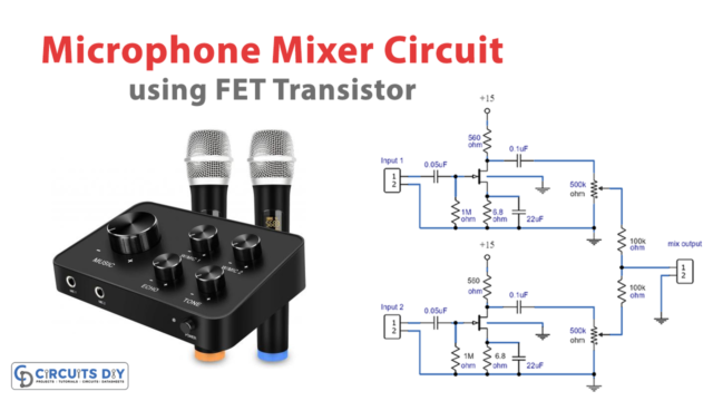
The objective of this project was to create a compact, portable mixer powered by a 9V PP3 battery while maintaining high-quality performance. This mixer consists of three primary modules, which can be customized in terms of quantity and arrangement to meet individual needs. These modules are:
- Input Amplifier Module: This module features a low-noise circuit with a variable voltage-gain range of 10 to 100, primarily designed for high-quality microphone inputs but also suitable for low-level line inputs. Additionally, an optional Balanced Input Amplifier Module with similar capabilities was included upon request.
- Tone Control Module: This module includes a three-band tone control circuit (Bass, Middle, Treble) that provides unity gain when set to a flat frequency response. It can be placed after one or more Input Amplifier Modules and/or after the Main Mixer Amplifiers.
- Main Mixer Amplifier Module: This stereo circuit incorporates two virtual-earth mixers and includes one Main Fader and one Pan-Pot connection.
The diagram below illustrates the entire mixer’s block diagram, featuring four Input Amplifier Modules followed by four Tone Control Modules that can be switched in and out, a stereo Line input, four mono Main Faders, a stereo dual-ganged Main Fader, four Pan-Pots, a stereo Main Mixer Amplifier Module, and two additional Tone Control Modules switchable for each channel before the main Left and Right outputs. This layout can be customized as desired.
One remarkable aspect of this design is its low power consumption; the complete stereo mixer, as depicted in the block diagram, consumes less than 6mA of current.

(1) Input Amplifier Module
The foundational structure of this circuit draws inspiration from the classic Quad magnetic pick-up cartridge module. However, it has been reconfigured to accommodate microphone input and operate on a single-rail low voltage power source.
This design features a low-noise, fully symmetrical head amplifier layout comprising two transistors. This layout enables the utilization of a standard FET input Operational Amplifier (Op-Amp) as the second gain stage, suitable even for highly sensitive microphone inputs.
The voltage gain of this amplifier can be adjusted using resistor R9, allowing for a range of 10 to 100, equivalent to 20 to 40dB.
Notes:
- R9 can be a trimmer, a linear potentiometer or a fixed-value resistor at will.
- When voltage-gain is set to 10, the amplifier can cope with 800mV peak-to-peak maximum Line levels.
- Current drawing for one Input Amplifier Module is 600µA.
- Frequency response is 20Hz to 20KHz – 0.5dB.
- Total Harmonic Distortion measured with voltage-gain set to 100: 2V RMS output = <0.02% @ 1KHz; <0.04% @ 10KHz.
- Total Harmonic Distortion measured with voltage-gain set to 10 & 33: 2V RMS output = <0.02% @ 1KHz & 10KHz.
- THD is much lower @ 1V RMS output.
- Maximum undistorted output voltage: 2.8V RMS.

| S.no | Components | Value | Qty |
|---|---|---|---|
| 1 | Integrated Circuit IC | IC1=TL061 | 1 |
| 2 | Transistors | Q1=BC560C 45v-100mA PNP Q2=BC550C 45v-100mA NPN | 1 1 |
| 3 | Polar Capacitors | C2,C8=100µF-25v C7=4µF7-63v | 1 1 |
| 4 | Non-Polar Capacitors | C1=470nF-63v C3,C4,C5=2µ2-63v C6=47pF-63v | 1 3 1 |
| 5 | Resistors | R1,R2,R7=22K-1/4w R3,R4,R5=47K-1/4w R6=4K7-1/4w R8,R13=220R-1/4w R9=2K-1/2w R10=470K-1/4w R11=560R-1/4w R12=100K-1/4w | 1 1 1 1 1 1 1 1 |
(2) Tone Control Module
The design is quite straightforward, employing Baxandall-type active circuitry with slight modifications to achieve a three-band control. When the controls are set to their midpoint, this module maintains a total voltage gain of 1.
Notes:
- Current drawing for one Tone Control Module is 400µA.
- Frequency response is 20Hz to 20KHz – 0.5dB, controls flat.
- Tone control frequency range: ±15dB @ 30Hz; ±19dB @ 1KHz; ±16dB @ 10KHz.
- Total Harmonic Distortion measured @ 2V RMS output = <0.012% @ 1KHz; <0.03% @ 10KHz.
- THD is below 0.01% @ 1V RMS output.
- Maximum undistorted output voltage: 2.5V RMS.

| S.no | Components | Value | Qty |
|---|---|---|---|
| 1 | Integrated Circuit IC | IC1=TL061 | 1 |
| 2 | Potentiometer | P1,P2=100k P3=470k | 2 1 |
| 3 | Polar Capacitors | C6,C8=100µF-25v C7=4µ7-63v | 2 1 |
| 4 | Non-Polar Capacitors | C1=1µF-63v C2=47nF-63v C3,C5=4n7-63v C4=22nF-63v | 1 1 2 1 |
| 5 | Resistors | R1,R2,R3=12k-1/4w R4,R5=3k9-1/4w R6,R7=1k8-1/4w R8,R9=22k-1/4w R10=560R-1/4w R11=100k-1/4w R12=220R-1/4w | 3 2 2 2 1 1 1 |
(3) Main Mixer Amplifier Module
The circuit schematic is depicted in stereo format to clearly illustrate the input connections for the Main Fader and Pan-Pot. Utilizing the TL062 chip, which houses two TL061 op-amps in an 8-pin configuration, this setup functions as two virtual-earth mixer amplifiers with a voltage gain of approximately 4. This gain compensates for losses in the passive Pan-Pot circuitry, resulting in a total voltage gain of 1.
When adding a new channel to the mixer, the following additional components are required: P1, P2, R1, R2, R3, R4, C1, and C2. These components should be connected according to the circuit diagram, with R3 and R4 linked to pin #2 and pin #6 of IC1 for the Right and Left channels, respectively. These pins on IC1 serve as the “virtual-earth mixing points,” capable of summing together numerous channels.
Notes:
- Current drawing for one stereo Main Mixer Amplifier Module is 800µA.
- Frequency response is 20Hz to 20KHz – 0.5dB.
- Total Harmonic Distortion measured @ 2V RMS output = <0.008% @ 1KHz; <0.017% @ 10KHz.
- THD is 0.005% @ 1V RMS output.
- Maximum undistorted output voltage: 2.8V RMS.

| S.no | Components | Value | Qty |
|---|---|---|---|
| 1 | Integrated Circuit IC | IC1=TL062 | 1 |
| 2 | Potentiometer | P1=100k P2=10k | 1 1 |
| 3 | Polar Capacitors | C3,C8=100µF-25v C6,C7=4µ7-63v | 2 2 |
| 4 | Non-Polar Capacitors | C1,C2=330nF-63v C4,C5=10pF-63v C6,C7=4µ7-63v | 2 2 2 |
| 5 | Resistors | R1,R2,=15k-1/4w R3,R4,R11,R12=100k-1/4w R5,R6=22k-1/4w R7,R8=390k-1/4w R9,R10=560R-1/4w R13=220R-1/4w | 2 4 2 2 2 1 |
To parts listed above should be added: one Main on-off SPST switch, a LED used as pilot-light with its dropping 2K2 1/4W series-resistor, DPDT switches to enable or omit Tone Control Modules as shown in the Block diagram, input and output connectors of the type preferred, one stereo dual-gang 100K potentiometer to fade the Stereo Line Input as shown in the Block diagram, battery clip, PP3 9V battery, knobs etc.