Printed circuit boards (PCBs) are by far the most common method of assembling modern electronic circuits. Comprised of a sandwich of one or more insulating layers and one or more copper layers that contains the signal traces and the powers and GNDs, the design of the layout of printed circuit boards can be as demanding as the design of the electrical circuit. Being an extremely intricate & difficult process, PCB designing is something that is often consider to be only handle by novices. But some issues related to PCB designing are so complex that even some PCB design pros have difficulty dealing with them. So, In today’s article, we will look into some common PCB design issues that you can face while designing your PCB & ways to resolve them.
PCB design issues come in two broad categories, those that affect the static or DC operation of the circuit, and those that most noticeably affect dynamic or AC circuit operation, especially at high frequencies.
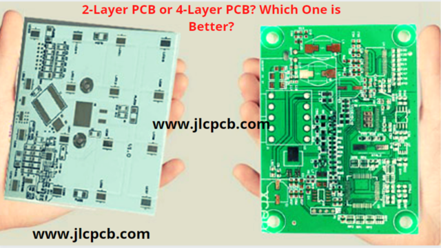
JLCPCB is the foremost PCB prototype & manufacturing company in china, providing us with the best service we have ever experienced regarding (Quality, Price Service & Time).
Common PCB Design Issues Faced in PCB Manufacturing

1) Vias Intruding Pads
Via intrusion in pads accumulative area can cause issues when the time comes for the board to be assembled. Via will draw solder away from the pad and cause the component associated with the pad to be improperly mounted.
2) Copper Trace Adjacent To Board Edge
Placing copper traces near the edge of the board can lead to shorts between the PCB layers when the PCB is dub down to size in the fabrication process. The DRC or DFM process usually helps in identifying & eliminating this type of design issue.
3) Incorrect Antenna Layout
When working with PCBs of high-speed wireless devices/products, the design layout of the antenna is very critical. Also, Impedance matching is very important to ensure max transfer of power between the transceiver and the antenna terminal. This sums up to two things, first is a microstrip of correct impedance (50 Ohm) connecting the antenna and the transceiver. In addition to that, it is also important to add an LC matching network such as a π – network.
4) Acid Traps
As the name implies, Acid traps occur when two traces join at a highly acute angle resulting in a possibility that the etching solution that removes copper from the blank board will get stuck/trap at these junctions. This cause traces to become disconnected from their assigned nets and leave these traces open circuited. The issue of Acid traps has been reduced in recent years by fabricators switching to the use of photo activated etching solutions.
5) Omission Of solder Mask
it is quite common for there to be no solder mask between pins due to standard design settings, usually due to the tight spaces between small pin pitch devices. The omission of said solder mask can lead to solder bridges forming more easily when the fine pin pitched component is attached to the PCB during assembly.
See Also: JLCPCB: The Right Way of Making Your PCBs & Assembling Your Board | PCB Terminologies – Common Terms Used In PCB Design | Common PCB Design Pitfalls To Avoid While Ordering Online