
RFID stands for Radio Frequency Identification; a term that refers to technologies that use radio frequencies to identify objects. RFID has been used in a number of practical applications in many industries, such as improving supply chain management, tracking household pets, accessing office buildings, and speeding up toll collection on roadways.
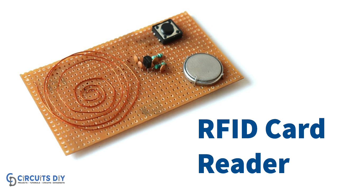
Being so useful & productive they do have a couple of shortcomings, such as not being cost-effective to buy & repair due to the complex nature of the embedded MCU (microcontroller units) in RFID receivers. So in this project, we are going to go over a step-by-step procedure on ‘How to make PCB Based RFID Card Reader” without using an Arduino OR any other kind of microcontroller.
JLCPCB is the foremost PCB prototype & manufacturing company in china, providing us with the best service we have ever experienced regarding (Quality, Price Service & Time).
Hardware Components
The following components are required to make RFID Card Reader Circuit
| S.no | Component | Value | Qty |
|---|---|---|---|
| 1. | Comparator IC | LM324 | 1 |
| 2. | Transistor | BC494, 2N2222 | 2 |
| 3. | Buzzer | 3.5V | 1 |
| 4. | Variable Capacitor | 33pF | 1 |
| 5. | Enameled Copper Wire | 25/16 gauge | 3 meters |
| 6. | Pushbutton | – | 1 |
| 7. | Diodes | 1N4148 | 1 |
| 8. | LED | 5mm | 1 |
| 9. | Ceramic Capacitor | 10pF, 82pF, 27pF | 1 |
| 10. | Resistors | 82K, 1K, 2.2M, 100K | 5 |
| 11. | Soldering Iron | 45W – 65W | 1 |
| 12. | Electrolytic Capacitor | 100uF | 1 |
| 13. | Veroboard | – | 2 |
| 14. | DC Battery with clip | 9V | 1 |
| 15. | Coin Cell | 3V | 1 |
| 16. | Jumper wires | – | as per need |
LM324 Pinout

For a detailed description of pinout, dimension features, and specifications download the datasheet of LM324
2N2222 Pinout
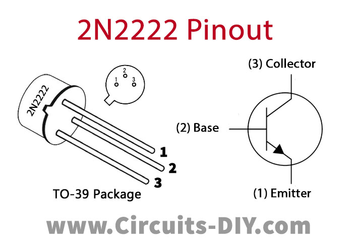
For a detailed description of pinout, dimension features, and specifications download the datasheet of 2N2222
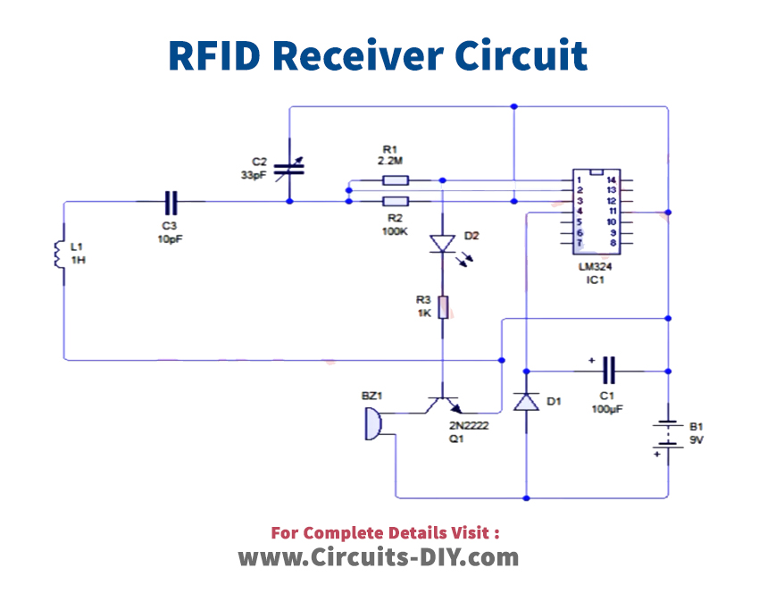
RFID Card Reader Circuit
Useful Steps
RFID Transmitter
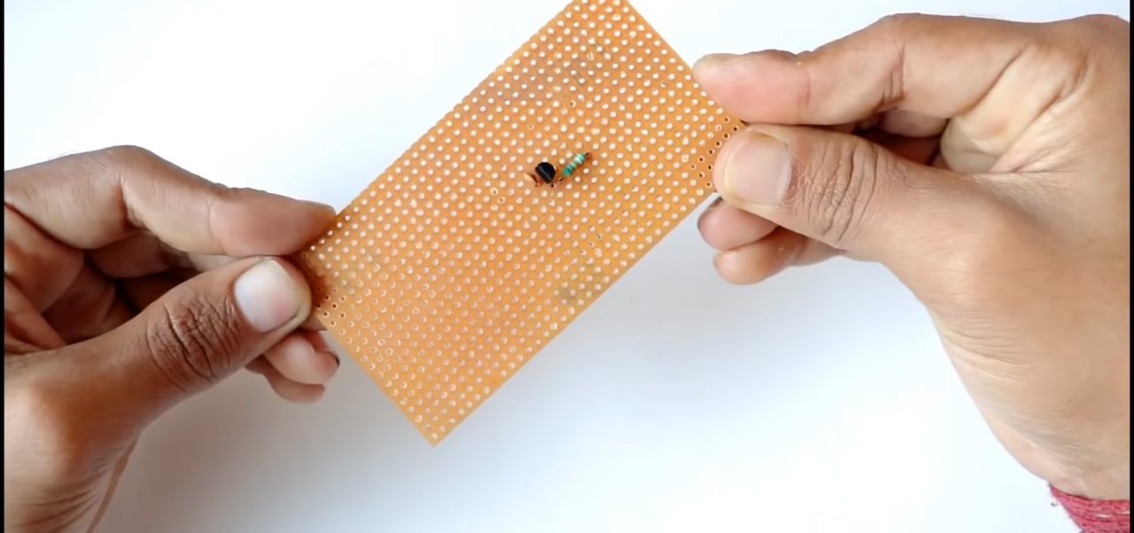
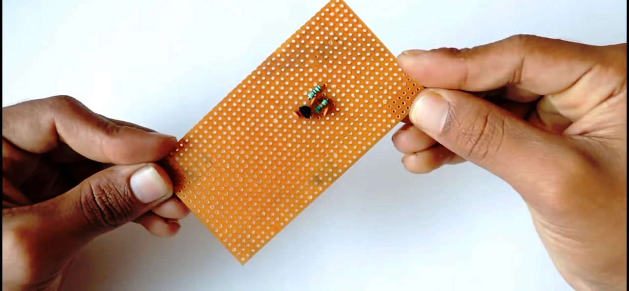
1) Solder the BF494 Transistor on the Vero board & solder an 82 K ohm resistor to the base of the transistor.
2) Solder the 10pF & 82pF capacitor parallel to the 82KOhm resistor.
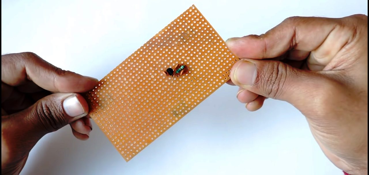
3) Solder the 1K resistor in series to the 82pF capacitor.
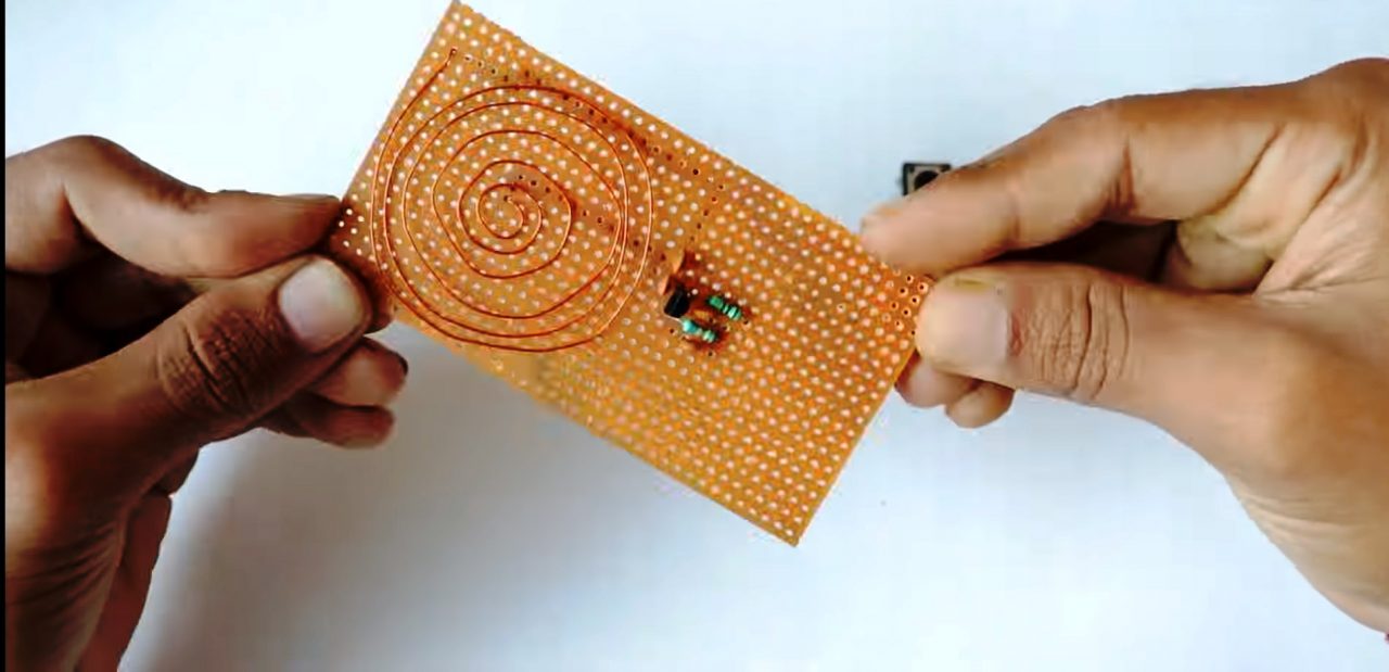
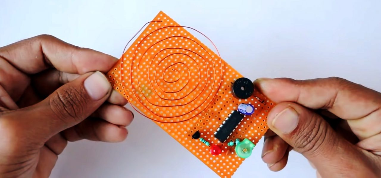
4) Coil the 25 gauge copper wire till 6 turns & solder one end with the collector of the transistor & other with the 27pF capacitor.
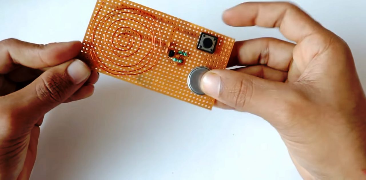
5) Solder the pushbutton & the coin cell on the Veroboard.
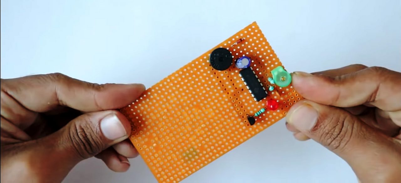
RFID Receiver
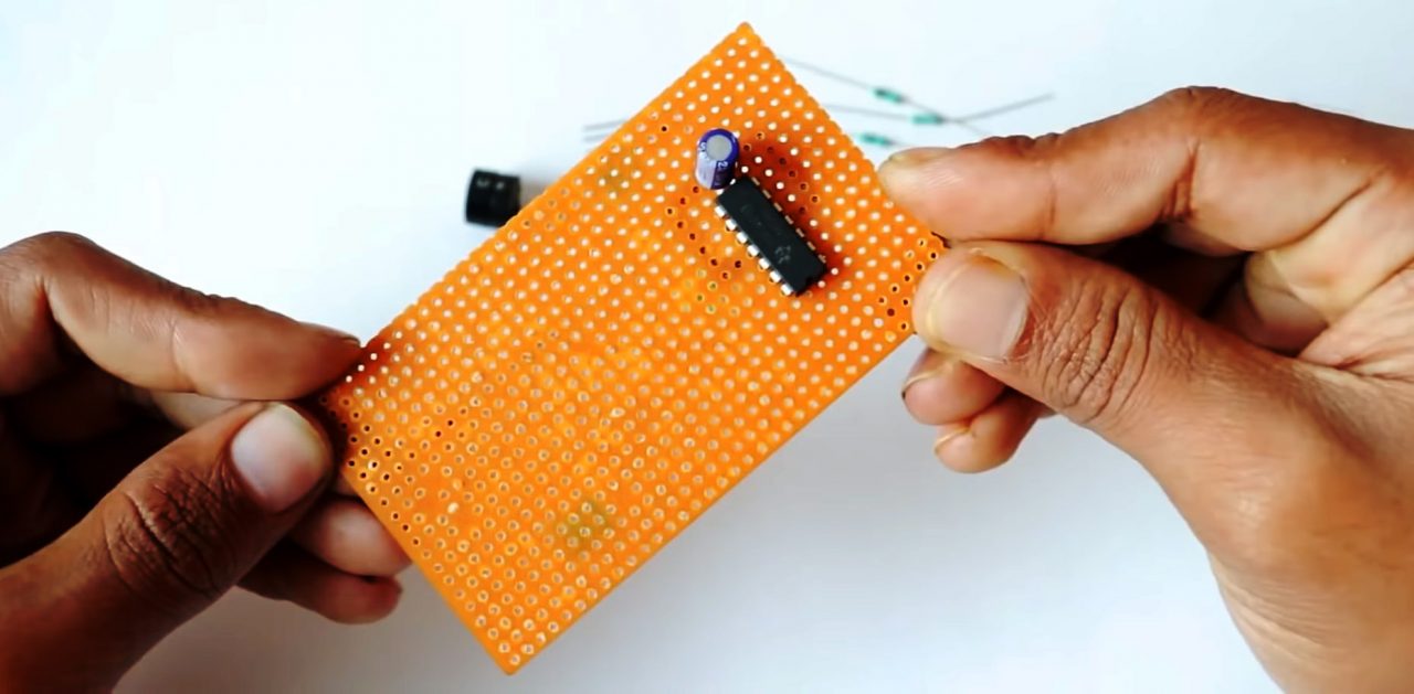
1) Solder the LM324 Comparator IC on the Veroboard. after that, solder a 100uF capacitor between pin 4 (+ve) & 11 (-ve) of the IC.
2) Connect 2.2M Ohm resistance between pins 1 & 2 of the IC. After that attach a 100K resistor between pin 2 & pin 3 of the IC.
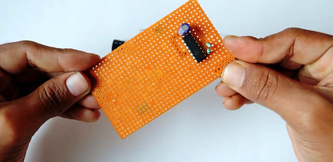
3) Solder a 33pF variable capacitor between pins 2 & 3 of the IC & a 10pF capacitor in series to the variable cap.
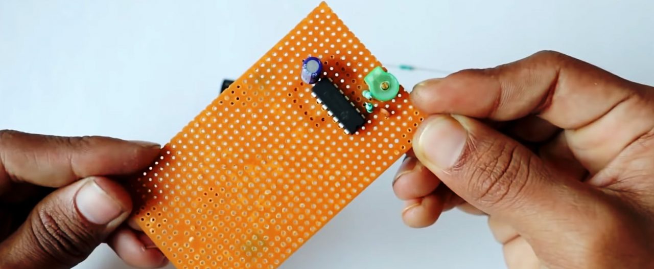
4) Connect the +ve pin of the LED on pin 1 of the IC. Connect the base of the 2n2222 transistor to the -ve terminal of the LED with a 1K resistor.
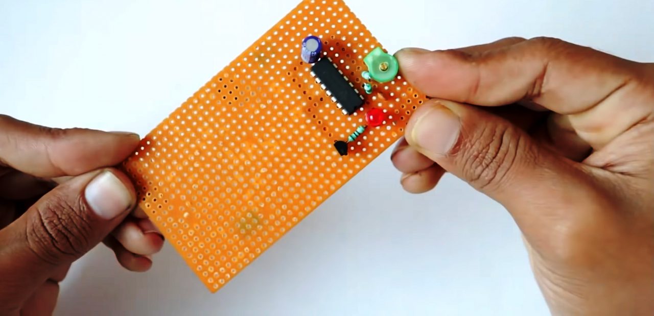
5) Connect the -ve terminal of the 5V buzzer to the collector of the transistor & connect the +ve terminal to the +ve of the 1N4148 Zener diode.
6) Connect a coil of 25 gauge copper wire between the 10pF capacitor & the emitter of the transistor.
7) Connect the +ve of the battery to pin 4 of the IC & -ve to pin 11.
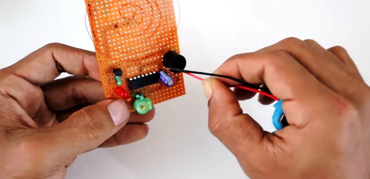
8) Power up & test the circuit
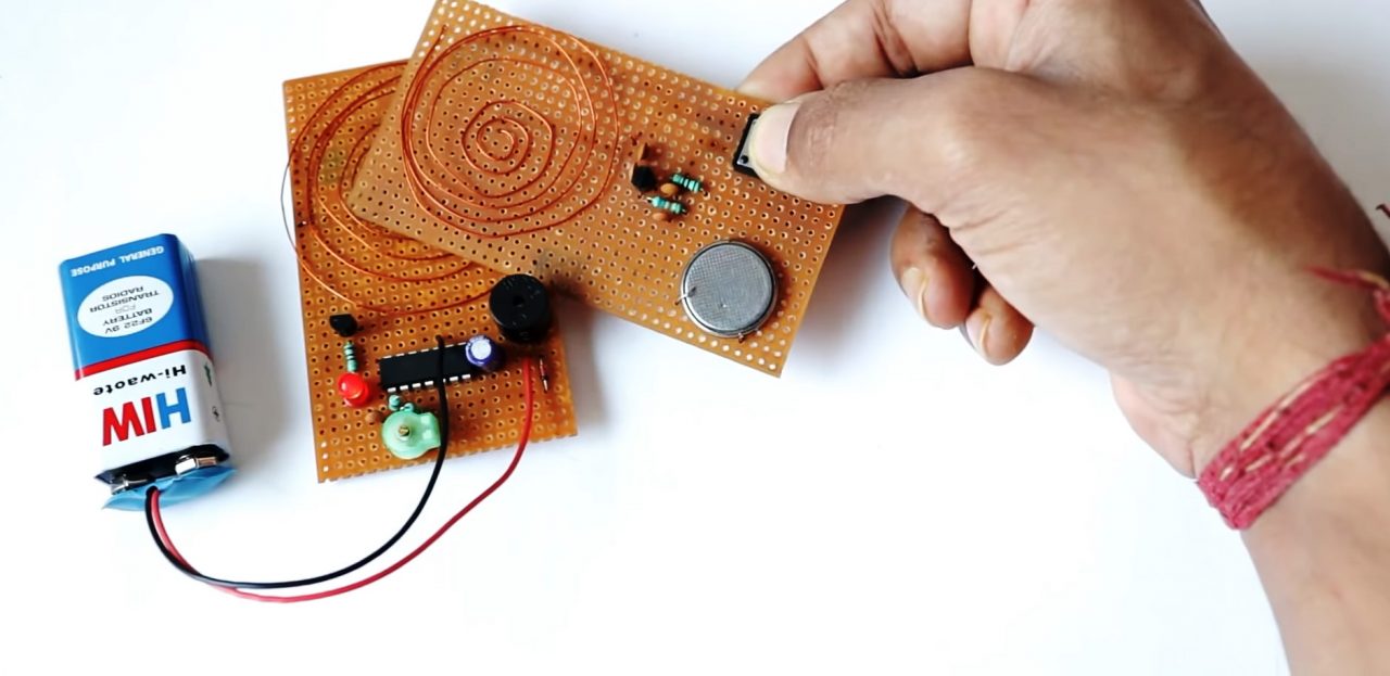
Working Explanation
The working of this circuit is very simple, on pressing the pushbutton of the transmitter the 1H copper coil inductor begins to generate its electromagnetic field. When the RFID receiver is brought into close contact with the transmitter, the 1H copper coil inductor generates an output due to mutual inductance between the 2 coils.
The output of the receiver coil is then fed to the 2 comparator inputs of the LM324 IC. The resultant output signal serves as a control signal to the base of the 2N2222 transistor which triggers the buzzer.
Applications
- Used in office/schools for attendance management.
- Also Used for inventory tracking.
- Used to avoid fraudulent/stolen products from malls and supermarkets.
Related posts:
 Reduce PCB Printing Cost | Top 5 Tips to Cut Cost During PCB Assembly
 JLCPCB - PCB Manufacturing & Assembly Services
 Why Choose JLCPCB For Your PCB Components Procurement Solutions
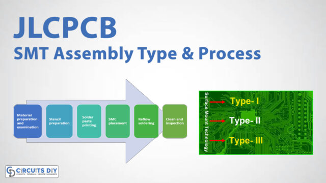 JLCPCB SMT Assembly Types and Assembly Process
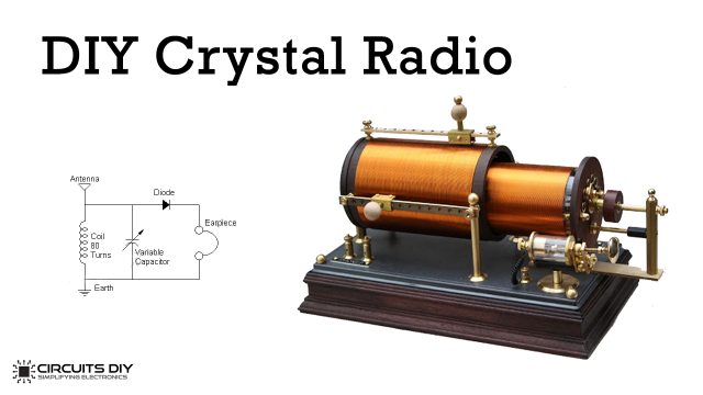 How to Make / Build a Crystal Radio
 PCBWay - Full Feature Custom PCB Prototype Service


