Introduction:
A filter as the name indicates is a device that removes or eliminates unwanted material and allows only the pure material to pass through. In electronic devices filter is used to eliminate the unwanted distortion or variation from the signal. Hence, by definition, a filter is a circuit that removes the AC components present in the rectified DC signal and allows only pure DC to pass through.
Passive Filter: Passive filter circuit is generally made using capacitors, inductors, or resistors. These circuits do not have any voltage gain due to no external source of energy. The combination of these passive components makes passive filters that the resistor allows the specific signal to pass through it. The following types of filters can be made using these passive components:
- Low Pass filter
- High Pass filter
- Band Pass filter
All these passive filters can be used according to the applications and their specifications.
Low-Pass Filter:
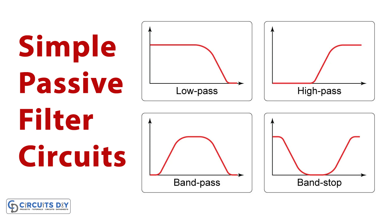
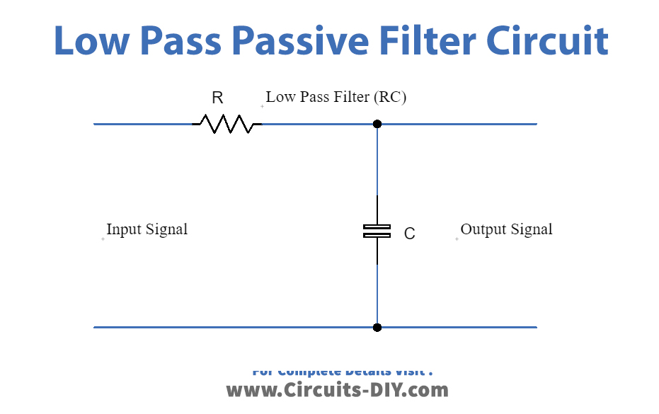
It allows low-frequency signals to pass through without decreasing the strength of the signal and blocks the high-frequency signal. It can be made using a resistor and capacitor across the input signal. The value of resistor and capacitor define the cut-off frequency of the filter, hence by changing their values cut-off value can be changed. Any frequency which exceeds the cut-off limit is rejected, and the rest is allowed to pass through.

The circuit diagram for the low-pass filter is given in the figure below:
High-Pass Filter:
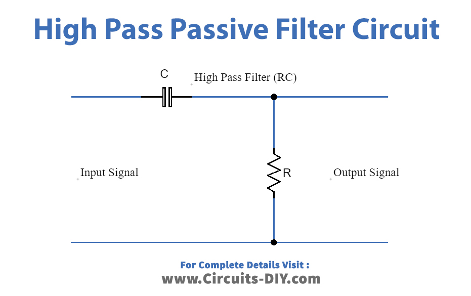
This type of filter allows the high-frequency signal to pass through and rejects the low-frequency signal without attenuating the input signal. It is also made using a resistor and capacitor in parallel to the input. The value of cut-off frequency is determined by the value of RC.

The circuit diagram for the high-pass filter is given below:
Band-Pass Filter:
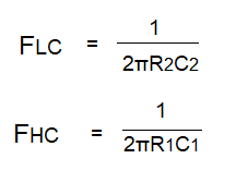
The bandpass filter is a type of filter that allows a particular band of frequencies to pass through while eliminating the other frequencies either lower or higher, therefore it has two cut-off frequencies that are lower cut-off and upper cut-off.
A bandpass filter is made of a low pass and high pass filters combined in a cascade order. The low pass filter rejects the high frequencies and the high pass filter rejects the low frequencies and thus allows the middle band of frequencies to pass.
The filters given above are designed using resistors and capacitors elements, but also can be designed using resistors and inductors elements.
Working Principle:
Passive filters connected in series block the harmonic frequency by presenting a high impedance value to the harmonic frequency. It works by exhibiting different values of impedance for resonant frequency. Commonly, filters are connected in parallel however they can be connected in series. The parallel configuration provides reactive power used to improve the power factor and diverts the harmonic current to the ground. By definition, passive filters in the parallel configuration are designed to be capacitive at basic frequency.
Applications:
Passive filters are applicable in numerous applications. Some are given below:
- Passive filters are used for rejecting noise from the communication systems.
- High pass filters are used in audio amplifiers, speaker systems, equalizers etc.
- Low pass filters are used in image processing to amplify the image.
- Filters can also be used in telephonic systems, they convert the signal audio frequency signal into a voice band signal.
- They can be used as an integrator and an anti-imaging filter.
- Bandpass filters can be applied in optics.


