Introduction
For any device or circuit, over and under voltages are harmful. Under voltages can generate light flickers while overvoltages can damage the whole device. Understand this by the example of motor, a motor may get burned because of low running voltages or because of high voltages. So, we comprehended that both the higher voltages and the lower voltages can do a greater amount of harm to any circuit. Hence, every device needs a voltage protection circuit that can indicate and protect the devices from high or low voltage. Thus, in this tutorial, we are going to Make an “Overvoltage and Under Voltage Protection Circuit”
The circuit uses the LM393 dual comparator IC, having a drainage current of 0.4mA. The IC is simple to connect, requires few external components, and is affordable to use.
Hardware Components
The following components are required to make an Overvoltage and Under Voltage Protection Circuit
| S.no | Component | Value | Qty |
|---|---|---|---|
| 1. | Relay | 12v | 1 |
| 2. | IC | LM393 | 1 |
| 3. | Diode | 1N4007 | 4 |
| 4. | Transistor | BC547, BC557 | 1,1 |
| 5. | Zenor Diode | 1N5225 | 1 |
| 6. | LED | 3 | |
| 7. | Variable Resistor | 5K | 1 |
| 8. | Resistor | 1K, 10K, 4.7K | 5, 2, 3 |
LM393 Pinout

For a detailed description of pinout, dimension features, and specifications download the datasheet of LM393
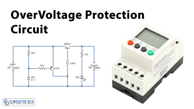
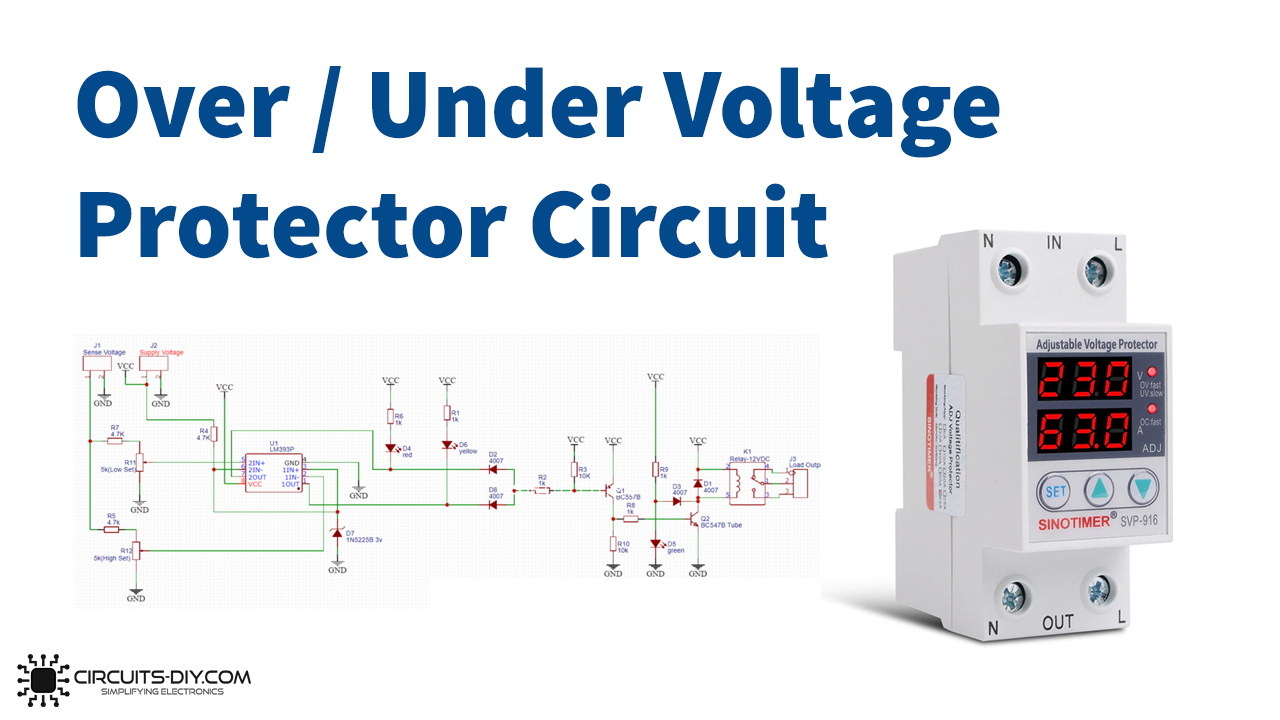
Overvoltage & Under Voltage Protection Circuit

Working Explanation
This Overvoltage and Under Voltage Protection Circuit needs two input voltages, the first is the 12V that is used to run the whole circuitry and the other is the variable voltage utilized to comprehend if the voltage is high or low. The relay is also wired in the circuit and it will only be turned on when the voltage is within the certain described limit. For this comparison, a comparator IC LM393 get utilized. There are two comparators in the IC, the first is used to set the lower threshold voltage and the other is used to set the higher threshold voltage. Hence, the potentiometer is used for this purpose. If the voltage is within a certain limit, the green LED turns on, and the relay can drive an external load. Otherwise, red and yellow LEDs glow for higher and lower voltages respectively.
Application and Uses
- It can be used to protect power transformers.
- Circuit breakers.
- In automation circuits, etc