In this tutorial, we are going to make an “Over Voltage and Reverse Voltage Protection Circuit”.
The protection ensures that the components are not damaged by an accidental swap of the power supply connections. Let’s say you accidentally applied too high voltage to your circuit or perhaps connect your batteries in reverse, over-voltage or reverse polarity can destroy your valuable work in seconds. When the overvoltage or surge spike comes then the load device will get affected. To avoid this situation, it’s one of the first things you’ll want to add to any circuit design that is simple Over Voltage and Reverse Voltage Protection. We design the circuit by using a few easily available components.
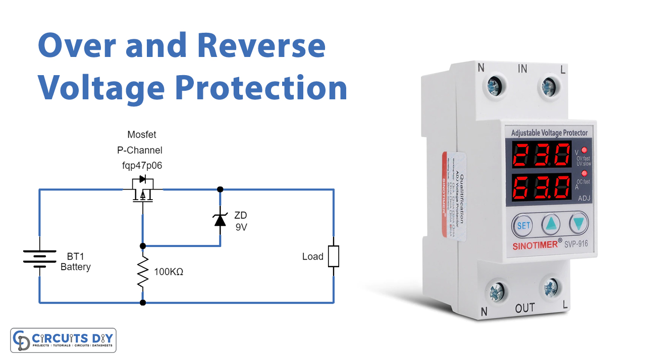
Here Mosfet and Zener diode are used as protecting elements. Because if we use a single PN junction diode as a reverse voltage protector then high reverse voltage or high forward current will burst the diode. For sensitive target load, this simple Over Voltage and Reverse Voltage Protection Circuit using MOSFET will be the right choice.
Hardware Components
The following components are required to make Voltage Protection Circuit
| S.no | Components | Value | Qty |
|---|---|---|---|
| 1. | MOSFET | FQP47P06 | 1 |
| 2. | Zener Diode | 9V | 1 |
| 3. | Resistors | 100KΩ | 1 |
| 4. | Connecting Wires | – | 1 |
| 5. | Power Supply | – | 1 |
FQP47P06 Pinout
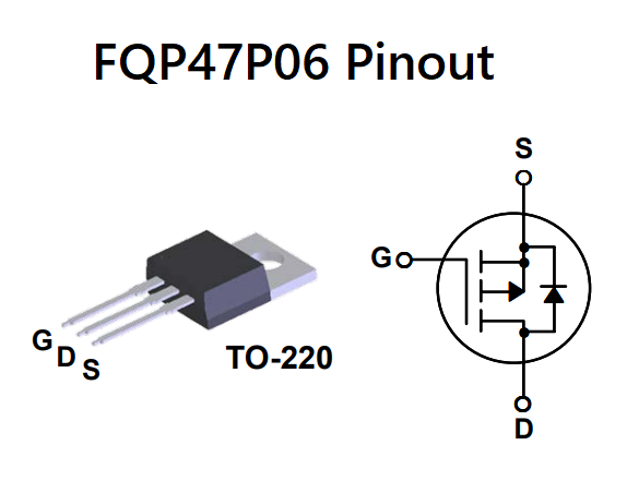
For a detailed description of pinout, dimension features, and specifications download the datasheet of FQP47P06
Voltage Protection Circuit
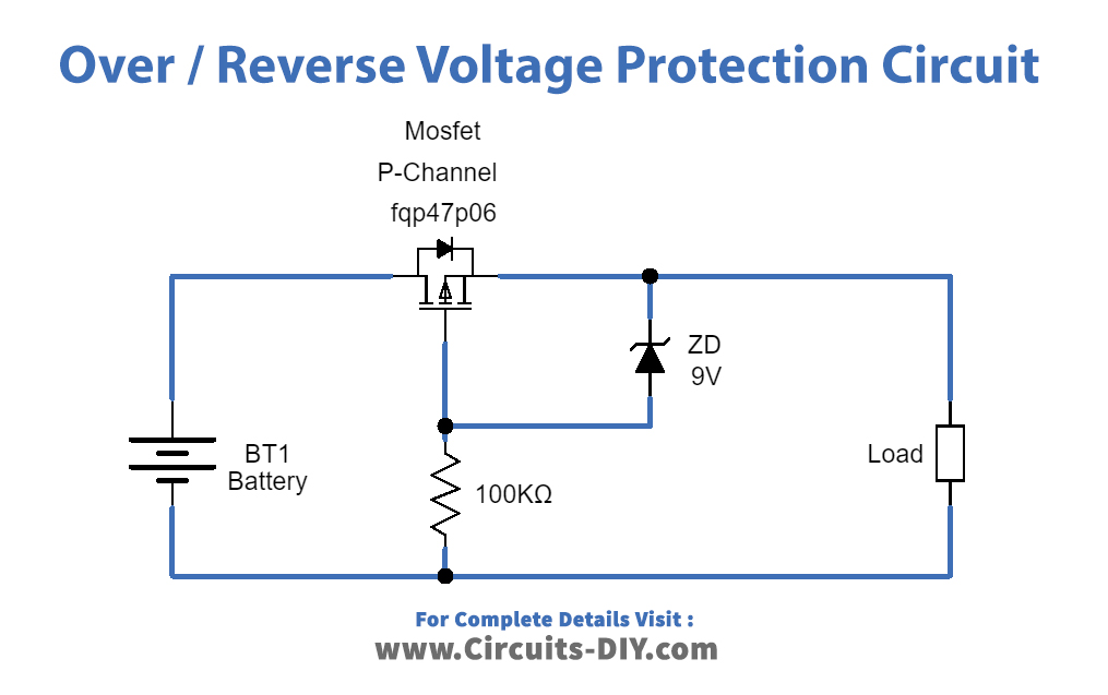
Working Explanation
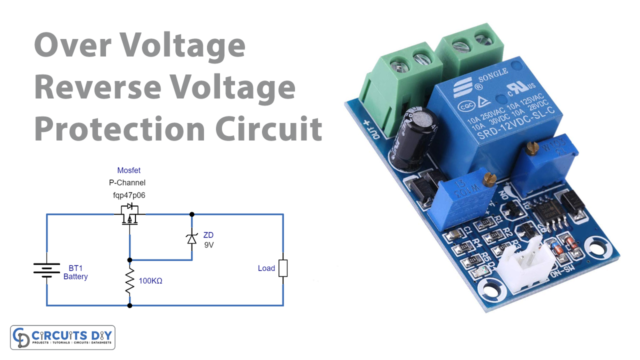
As we want, to get overvoltage and reverse polarity protection, we can use a low-side or high-side configuration for the protection circuit This circuit depends only on three elements, first one is P-Channel MOSFET FQP47P06, it is connected between the power source and target load and biasing Resistor R1, this MOSFET can control voltage over 60 Volt, it has three terminals called Gate, Drain, and Source. It has high avalanche energy strength (required for reverse voltage protection) and a high-speed switching character. Zener diode is connected between MOSFET Source and Gate terminal to provide Voltage Regulation at the output.
When we connect the supply to the target load at the right polarity and voltage then MOSFET allows the voltage supply to load and the Zener diode just acts as a forward-biased diode. When reverse voltage occurs then MOSFET p-channel holes will flow towards negative supply and create a barrier between Drain and source terminal hence there is no supply flow to the load. And if the right polarity is applied but the voltage increases beyond 9V then Zener breakdown occurs. So, the Zener diode regulates the voltage to 9V and allows the target load.
Applications
This is important in most electronic applications such as laptops, computers, CMOS circuits, etc.


