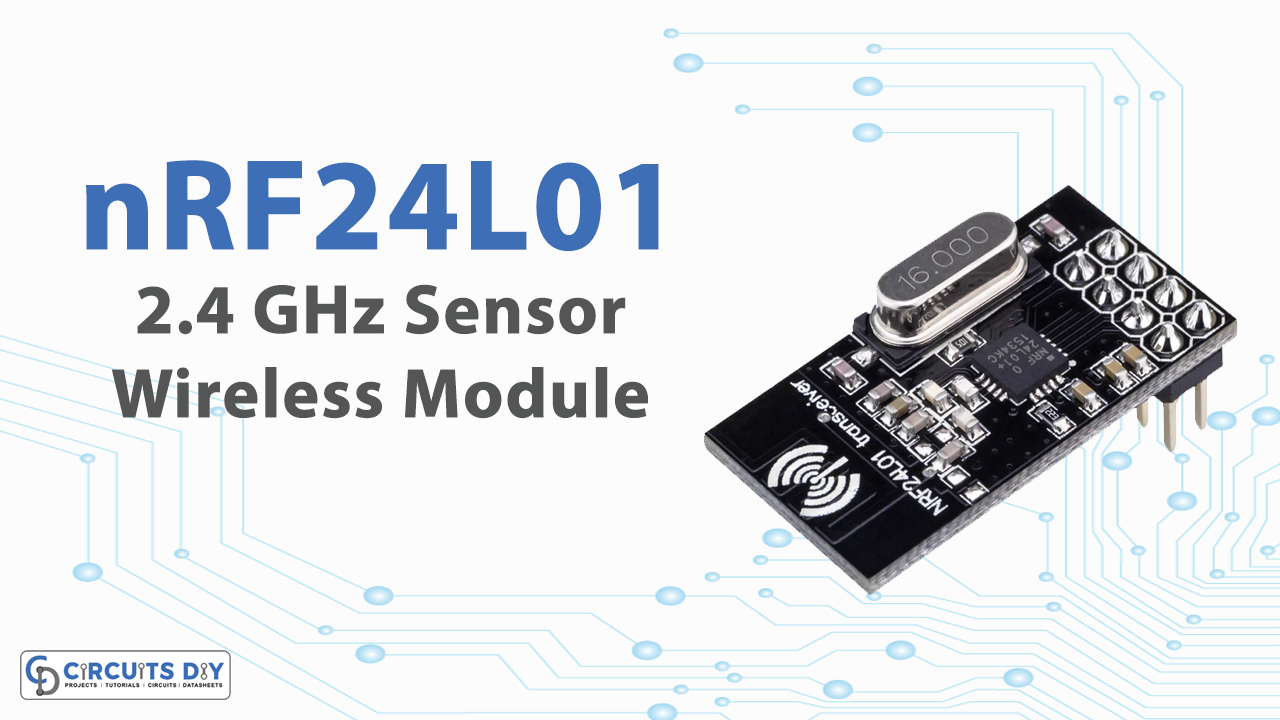
The world loves to interact wirelessly. And, with time are seeing fewer wires around. Electronic gadgets and components usually have no wires. These are because of the sensors inside. We are going to discuss one of those sensors, known as the nRF24L01 wireless module

Hardware Overview
The board of the module contains three pins for SPI communication and therefore they need to be connected to the SPI pins of the microcontroller. There are two more pins, CSN and CE, they are used for setting up the module in standby or active mode, and also for switching between transmitting or command mode. Both of these pins need to be connected to any digital pin of the microcontroller. The last pin is an interrupt pin that is used.
A module without an antenna is quite the same as a module with an antenna, where the antenna is part of the PCB. However, this without an antenna module makes the module to be more compact, but it also lowers the transmission range.
Working of Module
The nRF24L01+ transceiver module receives and transmits data on a certain frequency known as Channel. So, for two or more transceiver modules to communicate with each other, they demand to be on the same channel. This channel could be any frequency between 2.400 to 2.525 GHz. Each channel occupies a capacity of less than 1MHz. This makes 125 channels with 1MHz spacing. So, the module can use 125 different channels which gives a network of 125 independently working modems in one place.
Features and Specifications of nRF24L01 2.4 GHz
Features
- True single-chip GFSK transceiver
- Complete OSI Link Layer in hardware
- Enhanced ShockBurst™ protocol.
- Auto ACK (acknowledgment) & retransmit.
- Address and CRC (Cyclic Redundancy Check) computation.
- Data rate 1 or 2Mbps (normal condition)
- Digital interface (SPI) speed 0-8 Mbps
- 125 RF channel operation
- Short switching time enables frequency hopping
- Fully RF compatible with nRF24XX
- 5V tolerant signal input pads
- 20-pin package (QFN20 4x4mm)
- Uses ultra-low-cost +/- 60 ppm crystal
- Uses low-cost chip inductors and 2-layer PCB
Specifications
- Operating Voltage: 3.3V
- Nominal current: 50mA
- Range: 50 – 200 feet
- Operating current: 250mA (maximum)
- Communication Protocol: SPI
- Baud Rate: 250 kbps – 2 Mbps.
- Channel Range: 125
- Maximum Pipelines/node: 6
Pinouts of Sensor
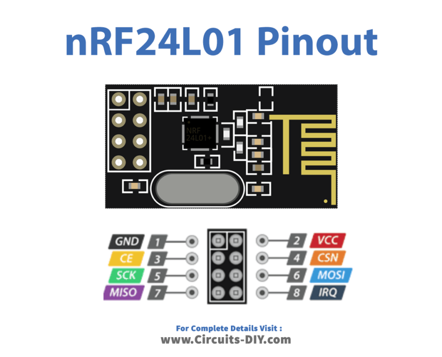
| No. | Pin Name | Description |
| 1. | GND | We used this to common ground |
| 2. | VCC | Supply pin (1.9 to 3.9V) |
| 3. | CE | This pin is a chip enable, it is used to activate RX or TX mode. |
| 4. | CSN | We use this pin for SPI protocol interfacing |
| 5. | SCK | We use this pin for serial clock providers. |
| 6 | MOSI | This is used to get data from a master microcontroller device and to send data to a slave device. |
| 7 | MISO | This pin is used to get data from a slave device and to send data to the master device. |
| 8 | IRQ | This pin is used to interrupt data. |
Applications
Wireless Devices
Since the sensor can connect wirelessly, therefore, can be used in wireless devices like wireless keyboards, and mice, to operate within the defined range of the sensor.
Security Systems
The sensor has wide applications in security alarms. For example, in wireless intruder alarms, etc.
Home Automation
To turn ON/OFF home appliances wirelessly, this sensor can be a superb choice. One can connect the sensor to the home and other automation systems.


