Introduction
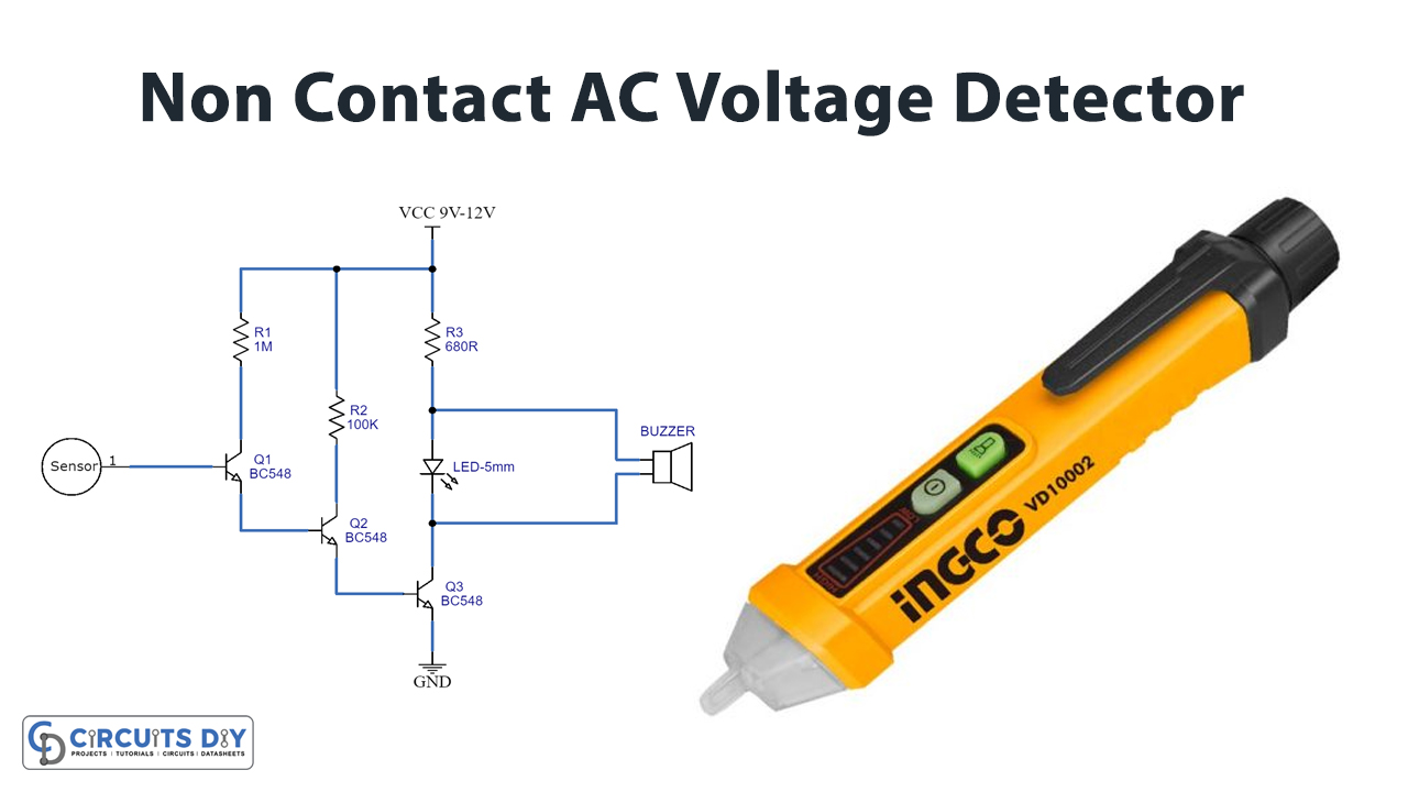
To detect various types of voltages, designers made different kinds of detectors that can simply give indications about DC or AC voltages. In short, they are mostly, used where devices need to determine the electric charge or field. Thus, voltage detectors are of different types including pulse or continuous DC voltage detectors and high or low-frequency AC voltage detectors. So, in this article, we’ll discuss the AC voltage detector and as the name implies, this circuit detects the alternating voltage without any contact.
Therefore, with the help of this circuit one can easily identify the presence of AC voltages. In other words, a voltage detector estimates the flux lines of the electric field that is created between the earth’s potential and a system. Hence to understand this, let’s move forward to make a “Non-Contact AC Voltage Detector Circuit Diagram”

Hardware Components
BC547
BC547 Pinout
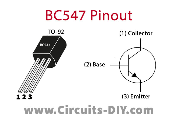
For a detailed description of pinout, dimension features, and specifications download the datasheet of BC547
AC Voltage Detector Circuit
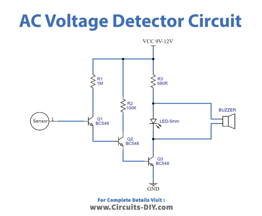
Working Explanation
Firstly, connect the Non-Contact AC Voltage Detector according to the circuit diagram given in this tutorial. After that, when you [provide the 9V supply to the circuit, the base of the transistor T3 catches the AC signal. But, this signal is not enough to turn on the buzzer or LED. So, transistors T2 and T1 are used to amplify the signals. As a result, they drive the buzzer and LED. And, this is how the circuit works.
Application and Uses
- Firstly, it is used in voltage monitoring systems.
- Moreover, in higher voltage protection systems.
- Further, in switching circuits.
- Also, to detect supply wires.


