Introduction
A non-contact voltage identifier or detector is an electrical analyzer that assists with recognizing voltage. Voltage presence is helpful data to have while troubleshooting requires. Thus, in this tutorial, we have decided to make a “Non-Contact AC Voltage Detector Circuit”. Non-contact voltage analyzers work by detecting a minimal amount of current that is capacitively coupled from the live circuit to the analyzer and back to the ground. Non-contact voltage analyzers light up when they identify this current without expecting to connect.
You may arise the question, that its working is the same as the multimeter, so what’s the difference? Both are not similar. The multimeter shows the exact reading of the voltage while this detector only senses or detects the voltage.
Hardware Required
| S.no | Component | Value | Qty |
|---|---|---|---|
| 1. | NPN Transistor | BC547 | 3 |
| 2. | Buzzer | 5v | 1 |
| 3. | LED | – | 1 |
| 4. | Switch | – | 1 |
| 5. | Wires | – | 1 |
| 6. | Resistor | 1MΩ, 100KΩ, 100Ω | 1, 1, 1 |
| 7. | Battery | 9V | 1 |
| 8. | 2-Pin Connector | – | 1 |
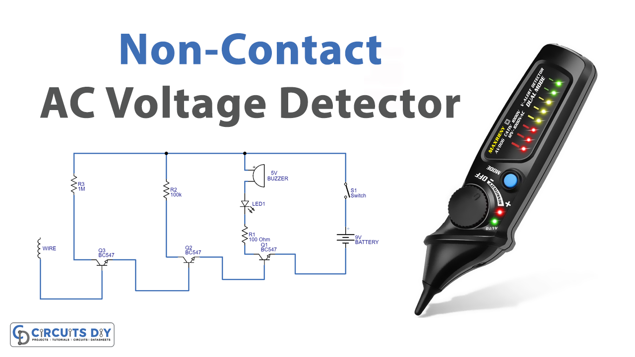
Circuit Diagram

Working Explanation
This Non-Contact AC Voltage Detector Circuit has the wire through which it senses the voltage. We connect the wire with the base of BC547 transistor Q3 which detects the EMF of supply. Then it gives the signal to another transistor Q2. Thus signal gets amplified and further goes to transistor Q1 which in this circuit is working as a switch. Hence when the signal arrives the switch on the emitter of Q1 gets closed. As a result, LEd glows, and the buzzer beeps.
Application and Uses
- In any application, to test the presence of AC voltage.

