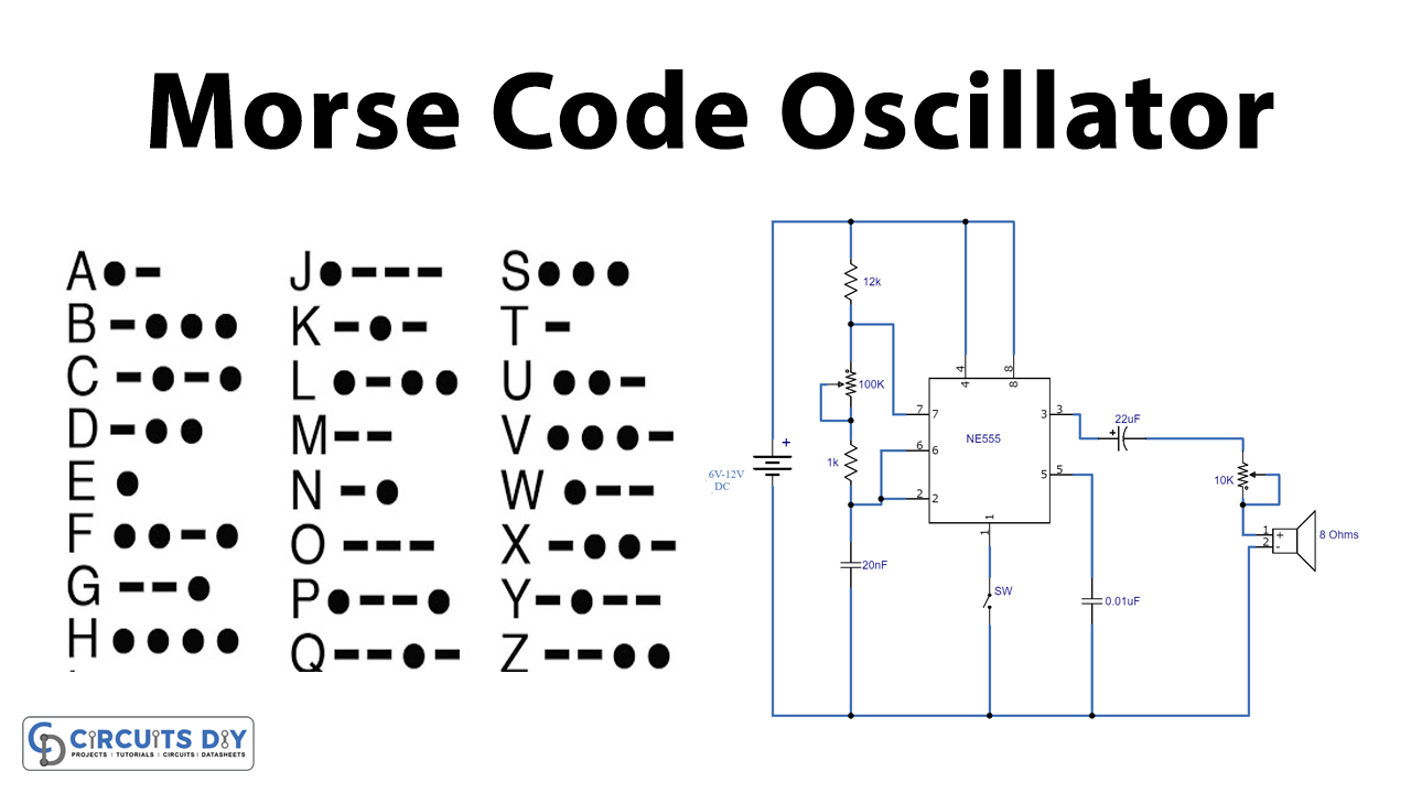
Morse Code encodes mainly all English Letters and numbers in standardized sequences. Each of the symbols is modeled into a sequence of Dashes and Dots. This method commonly serves in the field of telecommunication. Here is a simple electronic circuit to practice Morse code using oscillations from a NE555 timer IC.

Hardware Components
The following components are required to make Morse Code Oscillator Circuit
| S.no | Component | Value | Qty |
|---|---|---|---|
| 1. | IC | NE555 Timer | 1 |
| 2. | Speaker | 8Ω | 4 |
| 3. | Battery | – | 1 |
| 4. | Potentiometers | 100KΩ, 10KΩ | 1, 1 |
| 5. | Resistor | 12KΩ, 1KΩ | 1, 1 |
| 6. | Capacitor | 22µF, 10nF, 20nF | 1, 1, 1 |
| 7. | Breadboard | – | 1 |
| 8. | Switch | – | 1 |
| 9. | Connecting Wires | – | 1 |
NE555 IC Pinout

For a detailed description of pinout, dimension features, and specifications download the datasheet of 555 Timer
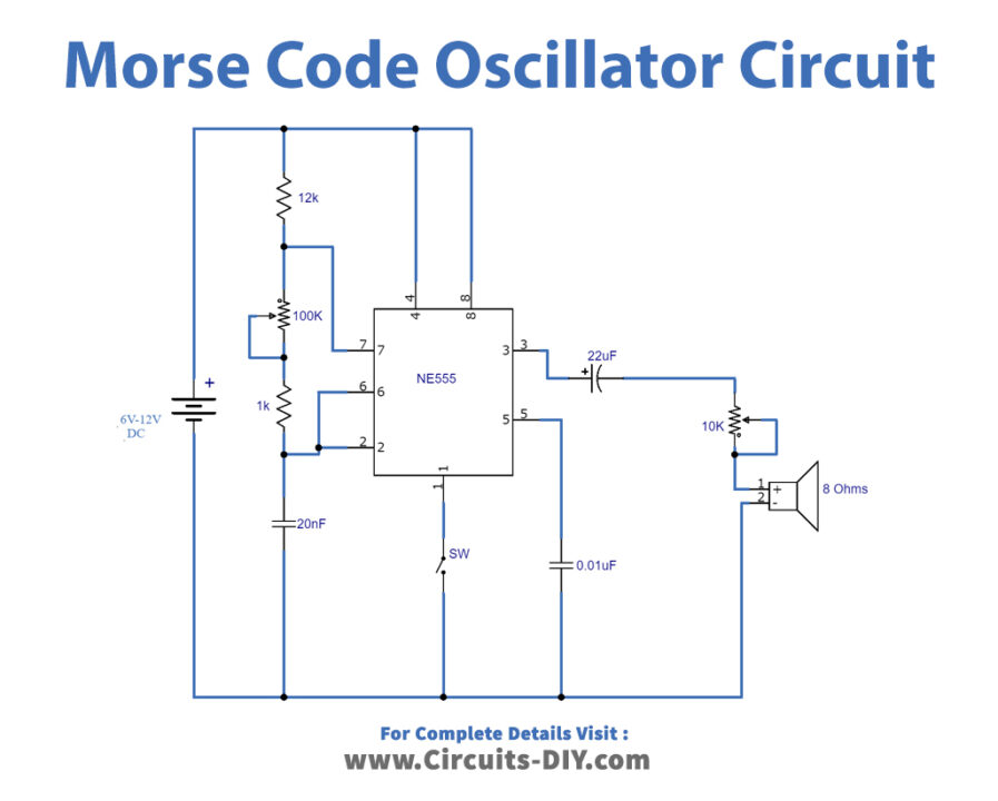
Morse Code Oscillator Circuit
Working Explanation
NE555, an old but versatile IC, is a precise timer IC producing accurate time delays and oscillations. Here in the circuit above, NE555 works in its Astable Multivibrator mode. The astable mode is such that the IC produces oscillations at a particular frequency, hence generating rectangular pulses.
The variable resistor adjusts the tone of the circuit. Moreover, using combinations of ON-OFF operation of the switch, the circuit can produce the desired Morse code. The operating voltage of the circuit ranges from 6V to 12V.
Application
- This project is used by amateur radio enthusiasts for the purpose of practicing Ham Radio. There’s now computer software available to fulfill the purpose but this circuit is still considered a portable option.


