Contents
hide
The MC145406 is a silicon-gate CMOS IC that combines 3 drivers and 3 receivers to fulfill the electrical specifications. The drivers feature true TTL input compatibility, slew-rate limited output, 300Ω power-off source impedance, and output typically switching to within 25% of the supply rails. The receivers can handle up to +25V while presenting 3 to 7kΩ impedance. Hysteresis in the receiver aids reception of noisy signals.
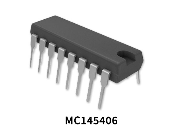
MC145406 Pinout
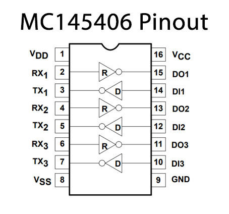
MC145406 Pin Configuration
| Pin No | Pin Name | Description |
|---|---|---|
| 1 | VDD | Drain Supply Voltage |
| 2 | RX1 | Receiver Pin 1 |
| 3 | TX1 | Transmitter Pin 1 |
| 4 | RX2 | Receiver Pin 2 |
| 5 | TX2 | Transmitter Pin 2 |
| 6 | RX3 | Receiver Pin 3 |
| 7 | TX3 | Transmitter Pin 3 |
| 8 | VSS | Source Supply Voltage |
| 9 | GND | Ground Pin |
| 10 | DI3 | Driver Input Pin 3 |
| 11 | DO3 | Driver Output Pin 3 |
| 12 | DI2 | Driver Input Pin 2 |
| 13 | DO2 | Driver Output Pin 2 |
| 14 | DI1 | Driver Input Pin 1 |
| 15 | DO1 | Driver Output Pin 1 |
| 16 | VCC | Collector supply voltage |
MC145406 Key Features
- Drivers
- +5 to +12V supply range
- 300Ω power-off source impedance
- Output current limiting
- TTL compatible
- Maximum slew rate = 30V/µs
- Receivers
- +25V input voltage range over the full supply range
- 3 to 7kΩ input impedance
- Hysteresis on input switch point
- General
- Very low supply currents for long battery life
- Operation is independent of power supply sequencing
You can download this datasheet for MC145406 EIA-232 Driver/Receiver from the link given below:


