The MAX232 of line drivers/receivers is intended for all communications interfaces, particularly applications where ±12V is not available. The MAX232 uses no external components and is recommended for applications where printed circuit board space is critical. The MAX232 is offered in 26 different packages with temperatures from 0 to +70°C up to -55°C to +125°C.
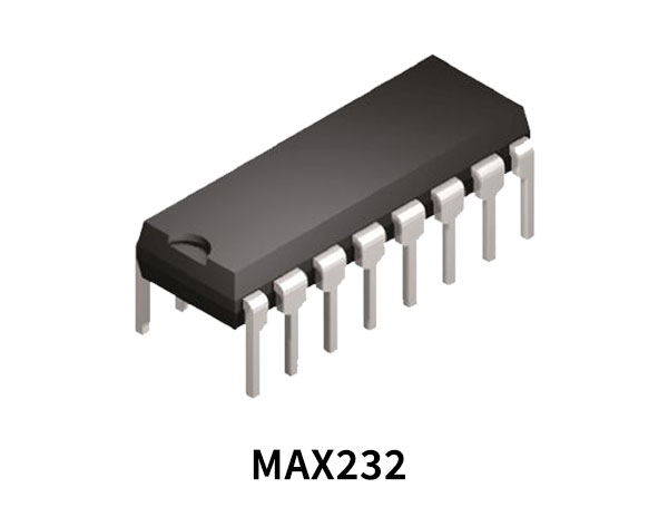
MAX232 Pinout
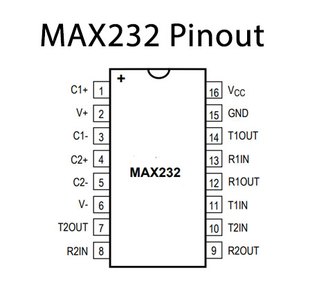
MAX232 Pin Configuration
| Pin No | Pin Name | Description |
|---|---|---|
| 1 | C1+ | Positive Capacitance Pin 1 |
| 2 | V+ | Positive Supply Voltage |
| 3 | C1- | Negative Capacitance Pin 1 |
| 4 | C2+ | Positive Capacitance Pin 2 |
| 5 | C2- | Negative Capacitance Pin 2 |
| 6 | V- | Negative Supply Voltage |
| 7 | T2OUT | Transmitter Output Pin 2 |
| 8 | R2IN | Receiver Input Pin 2 |
| 9 | R2OUT | Receiver Output Pin 2 |
| 10 | T2IN | Transmitter Input Pin 2 |
| 11 | T1 IN | Transmitter Input Pin 1 |
| 12 | R1 OUT | Receiver Output Pin 1 |
| 13 | R1 IN | Receiver Input Pin 1 |
| 14 | T1 OUT | Transmitter Output Pin 1 |
| 15 | GND | Ground Pin |
| 16 | VCC | Supply Voltage |
MAX232 Key Features
- Integrated Charge Pump Circuitry
- Eliminates the Need for a Bipolar ±12V Supply
- Enables Single Supply Operation from +5V Supply
- Integrated Capacitors (MAX223, MAX233, MAX235, MAX245–MAX247)
Application
- Interface Translation
- Multidrop RS-232 Networks
- Portable Diagnostics Equipment
You can download this datasheet for MAX232 Dual RS232 Receiver/Transmitter from the link given below:


