Introduction
In order to help the patients, engineers and designers are also doing their part since the frequency of heat-related illnesses and the number of those affected is increasing daily. The biomedical technologies used to monitor or identify a patient’s health may be recognizable to you. As a result, even little devices can have a significant influence on preserving human health. In this tutorial, the MAX 30102 Heart Rate Monitor one of those tiny sensors or monitors will be discussed.
Heart rate monitors are simple and inexpensive devices. You may access a variety of facts and data, depending on the device you use. You may use that information to build and monitor an activity plan, improve your health, and more.
What is Heart Rate Monitor?
Heart rate monitors are tools that can continuously detect and monitor your heart rate or pulse. Each pulse is detected, and the data is sent to a receiver such as a wristwatch, fitness gadget, or phone app. The number of beats per minute is shown as the data. Many of these wearable technologies are quite precise. Although these tools can be useful for keeping an eye on your health, they aren’t as precise as recognized medical devices.

Hardware Components
You will require the following hardware for the Heart Rate Monitor.
| S.no | Component | Value | Qty |
|---|---|---|---|
| 1. | Arduino | UNO | 1 |
| 2. | Heart Rate Monitor | MAX30102 | 1 |
| 3. | RGB Backlight LCD | 16×2 | 1 |
| 4. | Rotary potentiometer | – | 1 |
| 5. | LED | – | 1 |
| 6. | Resistor | 220 Ω | 1 |
| 7. | Breadboard | – | 1 |
| 8. | Jumper Wires | – | 1 |
Steps for Making Heart Rate Monitor
The steps to make this heart rate monitor are not difficult to follow. Once you got all the required components; follow the following steps:
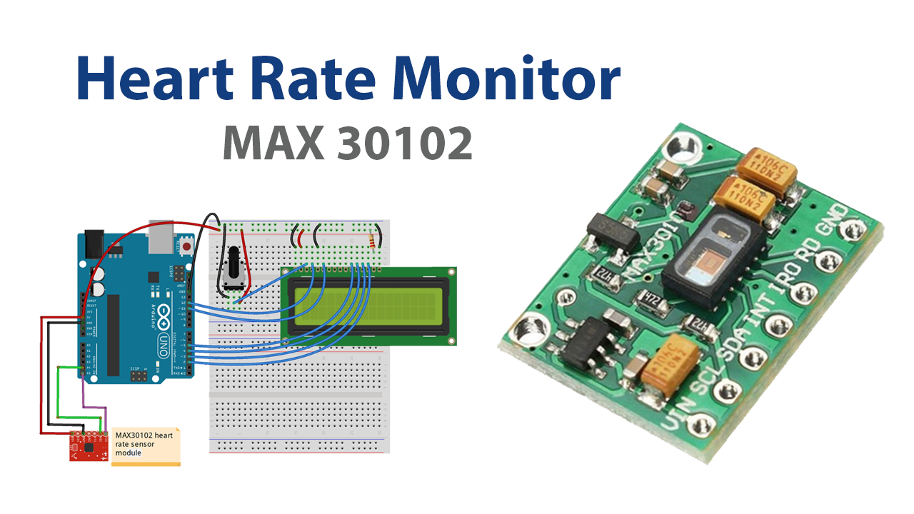
Schematic
Make connections according to the circuit diagram given below.

Installing Arduino IDE
First, you need to install Arduino IDE Software from its official website Arduino. Here is a simple step-by-step guide on “How to install Arduino IDE“.
Installing Libraries
Before you start uploading a code, download and unzip the following libraries at /Progam Files(x86)/Arduino/Libraries (default), in order to use the sensor with the Arduino board. Here is a simple step-by-step guide on “How to Add Libraries in Arduino IDE“.
Code
Now copy the following code and upload it to Arduino IDE Software.
#include <Wire.h>
#include "MAX30105.h"
#include <LiquidCrystal.h>

#include "heartRate.h"

MAX30105 particleSensor;
LiquidCrystal lcd(12, 11, 5, 4, 3, 2);

const byte RATE_SIZE = 4; //Increase this for more averaging. 4 is good.
byte rates[RATE_SIZE]; //Array of heart rates
byte rateSpot = 0;
long lastBeat = 0; //Time at which the last beat occurred

float beatsPerMinute;
int beatAvg;

void setup()
{
  Serial.begin(9600);

  lcd.begin(16, 2);
  Serial.println("Initializing...");

  // Initialize sensor
  if (!particleSensor.begin(Wire, I2C_SPEED_FAST)) //Use default I2C port, 400kHz speed
  {
    Serial.println("MAX30105 was not found. Please check wiring/power. ");
    while (1);
  }
  Serial.println("Place your index finger on the sensor with steady pressure.");

  particleSensor.setup(); //Configure sensor with default settings
  particleSensor.setPulseAmplitudeRed(0x0A); //Turn Red LED to low to indicate sensor is running
  particleSensor.setPulseAmplitudeGreen(0); //Turn off Green LED
}

void loop()
{
  long irValue = particleSensor.getIR();

  if (checkForBeat(irValue) == true)
  {
    //We sensed a beat!
    long delta = millis() - lastBeat;
    lastBeat = millis();

    beatsPerMinute = 60 / (delta / 1000.0);

    if (beatsPerMinute < 255 && beatsPerMinute > 20)
    {
      rates[rateSpot++] = (byte)beatsPerMinute; //Store this reading in the array
      rateSpot %= RATE_SIZE; //Wrap variable

      //Take average of readings
      beatAvg = 0;
      for (byte x = 0 ; x < RATE_SIZE ; x++)
        beatAvg += rates[x];
      beatAvg /= RATE_SIZE;
    }
  }

  Serial.print("IR=");
  Serial.print(irValue);
  Serial.print(", BPM=");
  Serial.print(beatsPerMinute);
  Serial.print(", Avg BPM=");
  Serial.print(beatAvg);

  if (irValue < 50000)
    Serial.print(" No finger?");

  Serial.println();

  lcd.setCursor(0,0);
  lcd.print("BPM: ");
  lcd.print(beatAvg);

  lcd.setCursor(0,1);
  lcd.print(" IR: ");
  lcd.print(irValue);
}
Let’s Test It
It’s now time to test the circuit. Keep your finger as steady as you can on the sensor after uploading the code and take a few seconds to wait for the data to make sense. You’ll observe the readings coming on the LCD.
Working Explanation
To understand the working of a circuit, you need to explore the coding a little!
- The required libraries are there to communicate the LCD and sensor. Some variables have been defined to use further in the code.
- The setup function initializes the LCD, serial monitor, and sensor. It also sets the sensor’s default settings.
- The excitement starts in the void loop! Here, it monitors the target patient’s heart rate in beats per minute or BPM.
Applications
- Fitness devices to monitor heart rate while working out.
- keeping an eye on your activities and stress levels during the day.
Conclusion.
We hope you have found this Heart Rate Monitor Circuit very useful. If you feel any difficulty in making it feel free to ask anything in the comment section.