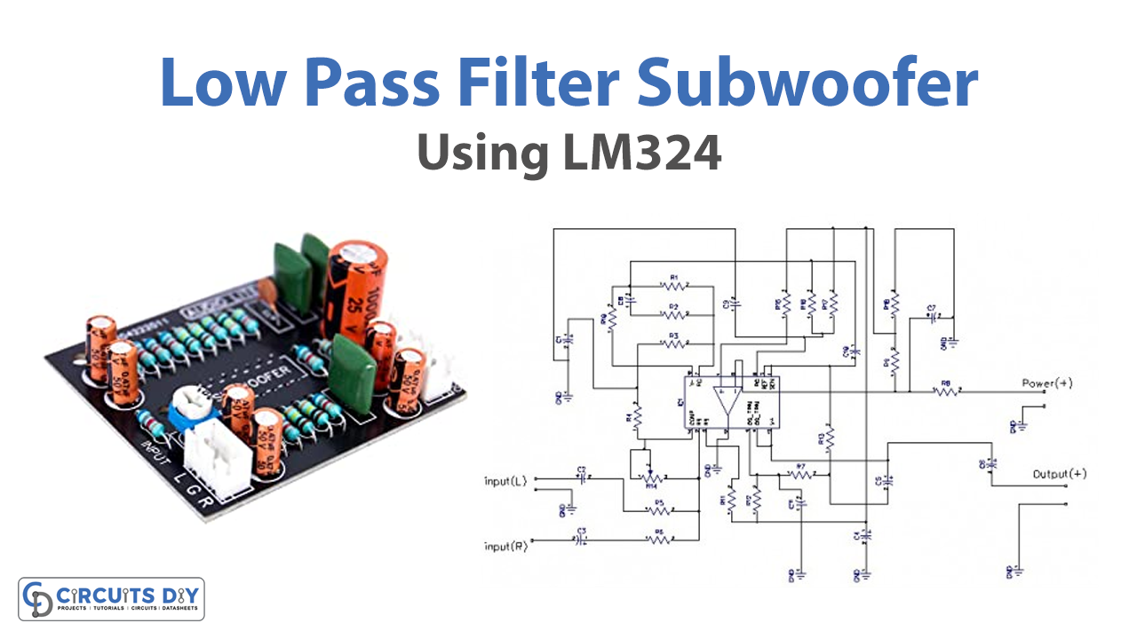
Subwoofers employ a low pass filter to play lower-frequency sounds. The subwoofer filter is a basic circuit that employs audio signals with low-pitched frequencies. The subwoofer frequency range is primarily defined as frequencies below 200Hz. They are designed to improve the bass response of a stereo system. In this post, we will design a low-pass filter for subwoofer circuits. To summarize, a low pass filter allows frequencies below a certain threshold to pass while blocking frequencies over that threshold. Hence, this tutorial is about making a “Low pass filter subwoofer using LM324”
Hardware Required
| S.no | Components | Value | Qty |
|---|---|---|---|
| 1 | IC | LM324 | 1 |
| 2 | Resistor | 100K, 6.8K, 47K, 4.7K, 470 ohm | 5, 7, 2, 2, 1 |
| 3 | Polar Capacitor | 0.47uF/25V, 47uF/25V, 0.22uF/63V, 2.2uF/50V, 470uF/16V | 3, 1, 1, 1, 1 |
| 4 | Ceramic Capacitor | 104 ACE, 473 AEO, 104J | 2, 1, 1 |
| 5 | Variable Resistor | 100K | 1 |
Circuit Diagram

Working Explanation
This circuit uses LM324 IC, the integrated circuit consists of four separate, high-gain, internally frequency-compensated operational amplifiers designed to operate over a wide range of voltages from a single power source. To prevent high frequencies from being played, subwoofer amps often employ LPF (low pass frequency) filters. The low pass filter controls the point at which low frequencies are sent to the subwoofer and high frequencies are sent to the mains. Thus, a subwoofer’s function is to authoritatively reproduce extremely low frequencies, which most loudspeakers often struggle to do on their own.

Application Uses
- Audio speakers
- Car sound system, etc


