Introduction
To play the lower notes of frequencies, a Low pass filter is used in subwoofers. The subwoofer filter is a fundamental circuit that uses low-pitched frequencies of audio signals. Mainly, the frequencies that are below the range of 200Hz are considered the subwoofer range of frequencies. They were made to expand the bass response in a stereo system. So, in this article, we will build a low-pass filter for subwoofer circuits. To sum up, a low pass filter passes the preferable low range of frequencies and blocks the frequencies which are above that range.
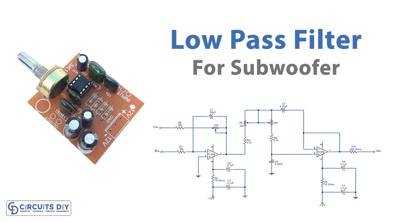
The circuit we are making is based on the dual high input impedance JFET operational amplifier IC. The circuit requires a dual power supply of 12 V. Remember, to mount the ICs on the holders. And, make sure to use a good quality board.
Hardware Required for Low Pass Filter
| S.no | Component | Value | Qty |
|---|---|---|---|
| 1. | PCB Board | – | 1 |
| 2. | Quad Op-Amp IC | TLC062 | 1 |
| 3. | Resistor | 10 ohms, 220 ohms, 4.7K, 39K | 2, 1, 2, 2 |
| 4. | Capacitor | 0.1uf, 0.22uf, 0.47uf, 39pf | 4, 1, 1, 1 |
| 5. | Dual power supply | 12V | 1 |
| 6. | Potentiometers | 22K, 47K | 2, 1 |
Circuit Diagram
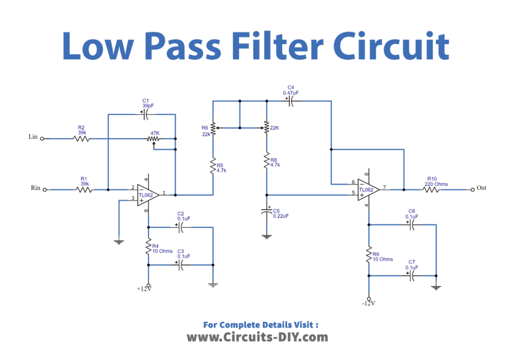
Working Explanation
The low-pass filter circuit for the subwoofer contains two stages. The first stage is working as a mixer. Both left and right channels are given at the inverting input pins of the IC. Potentiometer R3 is there to adjust the gain of the first stage. The output of the first stage is wired with the second stage of buffer through potentiometer R6 and other capacitors and resistors. As a result, you can observe the filtered output at pin 7 of the IC of the buffer stage.
Application and Uses
Besides the subwoofer, it can be used in:
- Audio speakers.
- Audio amplifiers.
- Equalizers, etc