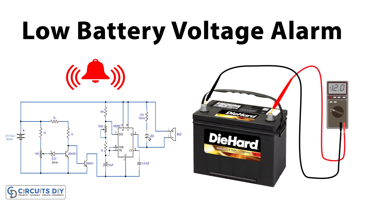
One of the primary reasons that weaken the rechargeable batteries is deeply discharging them to make the batteries work longer involves treatment for them. Each time a battery gets discharged its output decreases to some degree and the battery is destroyed very early by constant deep discharging.
For your rechargeable batteries to last longer, you don’t have to let them out completely discharged. A very useful circuit shown here can do this job very effectively by alarming when the battery has exceeded a certain amount of voltage

Hardware Components
The following components are required to make Low Battery Indicator Alarm Circuit
| S.no | Component | Value | Qty |
|---|---|---|---|
| 1. | Resistors | 1K, 10K, 470 ohms | 4,1,1 |
| 2. | Capacitors | 10uF, 0.01uF | 1,1 |
| 3. | Potentiometer | 10K, 100K ohms | 1,1 |
| 4. | IC | NE555 Timer | 1 |
| 5. | LED | 5mm | 1 |
| 6. | Buzzer | – | 1 |
| 7. | Transistor | 2N4401 | 1 |
| 8. | Battery | 12V | 1 |
NE555 IC Pinout

For a detailed description of pinout, dimension features, and specifications download the datasheet of 555 Timer
Low Battery Indicator Alarm Circuit
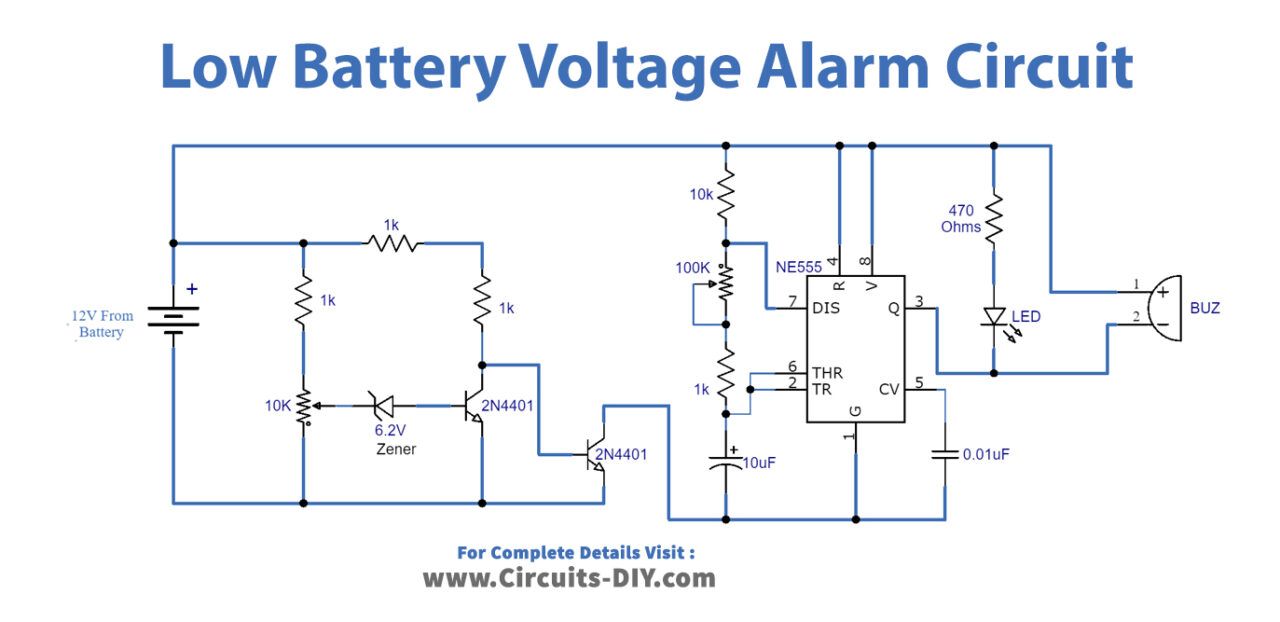
Working Explanation
A very useful circuit shown here can do this job very effectively by warning when your battery has reached a certain voltage point, for example when it is 90 percent empty, a 12V lead-acid battery shows 11.6. So change the 10 K variable resistor circuit to warn until the battery hits that amount or set the warning circuit when the battery hits 11.8 V or 11.9 V. Two transistors and a 555 timer IC are used at the circuit. As the battery runs down and reaches the preset level it will send beep signals and flash an LED. With the 100 K variable resistor, the beeping signals and the LED flash rate can be changed. No external power supply will be needed for the circuit, and it will run on the same battery.
Application and Uses
- It is used as an indication alarm for the low voltage battery


