In this tutorial, we are making a Long-Range Arduino Based Walkie Talkie using nRF24L01. although this is the era of 5G and smartphones and old technologies are not that commonly used but where short-distance, remote and low-cost communication is required these walkie talkie systems are more convenient than phones or other communication devices. The walkie talkie that we are making in this project can communicate among 6 people at a time and has a long-range. You can make short-range systems too by modifying this circuit.
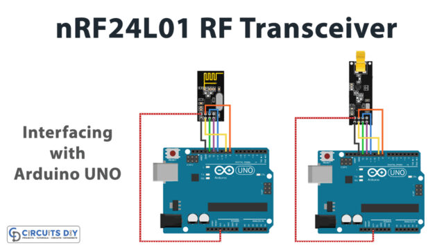
This circuit is using an nRF24L01 RF module as its main component. This module has a lot of advantages over a digital communication medium, it does not overlap or disturb other walkie talkie police and railway walkie-talkie. It consumes low power and it can communicate with six other nRF24L01 modules at one time when they are in the receiving state. The other important component or the processor of this circuit is Arduino Uno.
Hardware Required
| S.no | Component | Value | Qty |
|---|---|---|---|
| 1. | Li-ion battery | 5V | 2 |
| 2. | Battery charging and protection module | – | 2 |
| 3. | Arduino | any | 1 |
| 4. | RF module | NRF24L01 +PA+LNA with external 2DB antenna | 2 |
| 5. | Audio Amplifier | – | 2 |
| 6. | Microphone | – | 1 |
| 7. | DC to DC step-up booster module | – | 2 |
| 8. | voltage regulator module | AMS1117 3.3V | 1 |
| 9. | LED | – | 2 |
| 10. | Resistor | 470 ohms, 1K | 2, 2 |
| 12. | Capacitor | 104PF, 100NF | 2, 2 |
| 14. | Loudspeaker | 4-inch | 2 |
| 15. | Pushbutton | – | 2 |
Circuit Diagram
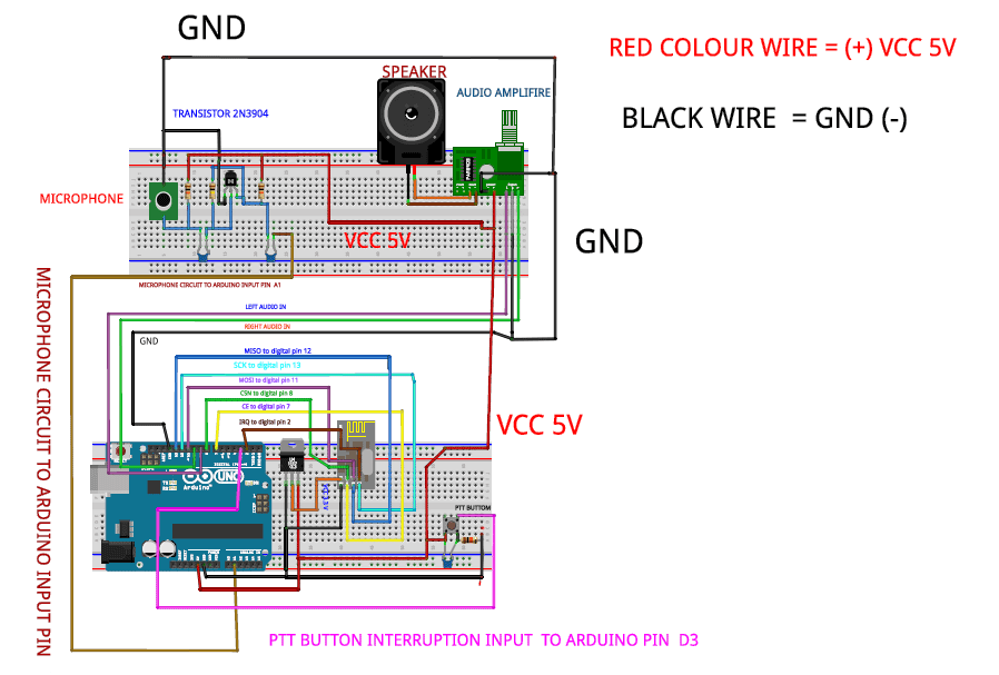
Working Explanation and Construction
This circuit is made on a PCB you can either purchase it or make a custom one by using an Arduino Atmega328p board. Put the Atmega 328 IC on the programmer, flash it, and then upload the code on it. Then add 16MHz crystal on Atmega328 IC. in this way you can make your custom PCB. The next step is to connect the NRFL24L01 modules as shown in the circuit diagram, the operating voltage of this circuit is 1.9-3.6V and a 100nF capacitor is used for current stability. Since the power supply is providing a voltage of 5 volts, you will have to drop it from 5 to 3.3V by using a 3.3V voltage regulator.
Now make a connection of the microcontroller digital pin no. 9 and 10 to the audio amplifier. We are using an audio amplifier because by default the Arduino’s output is very low. This amplifier needs 3.7-5V to operate and it gets its input voltage from the Arduino as shown in the circuit diagram.
The PTT switch is made using a simple push-button and a 0.1uF/104PF capacitor to prevent erratic signals when the switch is pressed. Arduino board receives an Arduino interrupt on its D3 pin. if the o/p of this pin is low then the walkie-talkie is in receiving, and when it is high it switched the walkie talkie into a transmitted mode so that you can send a voice signal.
After building the circuit enclose it in a small suitable enclosure. This circuit is compact so it can be easily used as a walkie-talkie.
Arduino Code
#include <RF24.h>
#include <SPI.h>
#include <RF24Audio.h>
#include "printf.h"    // General includes for radio and audio lib
RF24 radio(7,8);    // Set radio up using pins 7 (CE) 8 (CS)
RF24Audio rfAudio(radio,0); // Set up the audio using the radio, and set to radio number 0
int talkButton = 3;
void setup() {
  Serial.begin(115200);
  printf_begin();
  radio.begin();
  radio.printDetails();
  rfAudio.begin();
  pinMode(talkButton, INPUT);
  //sets interrupt to check for button talk abutton press
  attachInterrupt(digitalPinToInterrupt(talkButton), talk, CHANGE);
  //sets the default state for each module to receiver
  rfAudio.receive();
}
//void talk()
//Called in response to interrupt. Checks the state of the button.
//If the button is pressed (and held) enters transmit mode to send
//audio. If button is release, enters receive mode to listen.
void talk()
{
  if (digitalRead(talkButton)) rfAudio.transmit();
  else rfAudio.receive();
}
void loop()
{
}
Applications and Uses
- Construction Workers
- Smart helmets


