

Introduction
Let’s assume that you want to control an AC appliance, either an AC light or a motor, etc through the switch. So, what would you do? You may think to connect that appliance, for example, the motor in series with the switch and then to the main power. But it may waste energy because at a long distance, there would be a high resistive loss. In that case, your case you can use the high gauge wires.
However, these wires are quite expensive. So, to reduce both of the problems, there is a solution to use a Light-dependent resistor that operates the circuit with the help of LED light. The circuit turns ON when there is no light and turns OFF when the light falls on LDR. To understand the whole process, in this tutorial, we are going to make a “Long Distance Transmission System Circuit”
Hardware Components
The following components are required to make Long Distance Transmission System Circuit
| S.no | Component | Value | Qty |
|---|---|---|---|
| 1. | Relay | 12v | 1 |
| 2. | Transistor | BC547 | 2 |
| 3. | Resistor | 1K, 2.2K | 2, 1 |
| 4. | Diode | 1N4007 | 1 |
| 5. | LDR | – | 1 |
| 6. | LED | – | 1 |
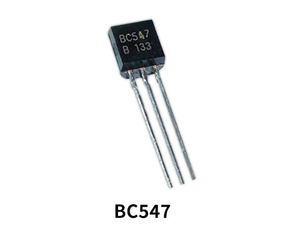
BC547 Pinout

For a detailed description of pinout, dimension features, and specifications download the datasheet of BC547
Long Distance Transmission System Circuit
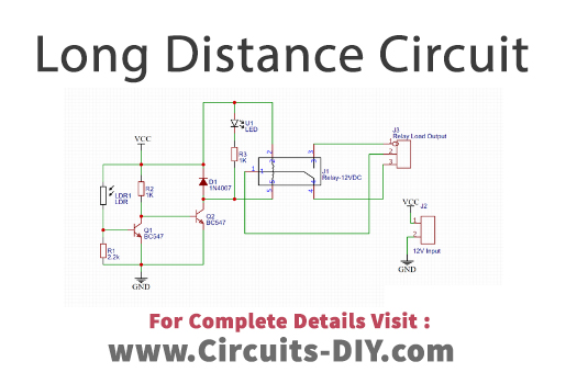
Working Explanation
This Long-Distance Transmission System Circuit uses LDR to operate. When there is no light the current flows from resistor R2 and triggers the base of the transistor Q2. Transistor Q2 is connected with the relay circuit, which is driving the load. So, when the light doesn’t fall on the LDR circuit, the relay turns on and drives whatever the load is attached. When the light falls on the LDR, now current flows to the transistor Q1. In that case, Q1 remains OFF and ultimately turns OFF the relay.
Application and Uses
- You can drive different AC loads through this circuit, for example, you can operate a motor through that.


