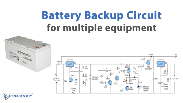
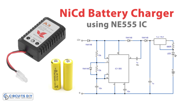
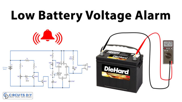
In this tutorial, we are making an LM3914 Automatic 12V / Universal Battery Charger. The IC that we are using is LM3914 which is used to sense voltage levels of power supplies and batteries. But in our circuit with some modifications, it is used as an automatic battery charger.
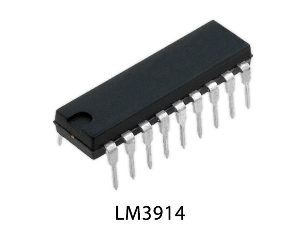
Hardware Components
The following components are required to make Automatic Battery Charger Circuit
| S.no | Component | Value | Quantity |
|---|---|---|---|
| 1. | Power Supply | 15V | 1 |
| 2. | Transistor | 2N4403, 2N4401, TIP127 | 1, 2, 1 |
| 3. | Heatsink | – | 1 |
| 4. | IC | LM3914N | 1 |
| 5. | LED | – | 10 |
| 6. | Resistor | 2.2K, 1K, 10K, 4.7K, 5.1K, 560R, 56K | 1, 2, 1, 3, 1, 1, 1 |
| 7. | Potentiometer | 10K, 250K | 1 |
| 8. | Diode | 1N5823 | 1 |
LM3914 Pinout
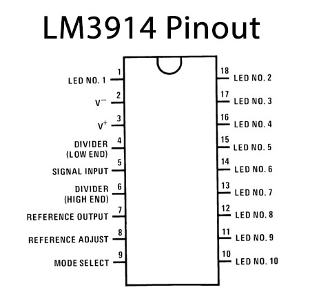
For a detailed description of pinout, dimension features, and specifications download the datasheet of LM3914
2N4401 Pinout

For a detailed description of pinout, dimension features, and specifications download the datasheet of 2N4401
Automatic Battery Charger Circuit

Working Explanation
The IC that we are using in this circuit can sense voltage levels and drives 10 LEDs providing a display for each level of the battery. This circuit is built around four transistors. The base of the transistor Q1 should be attached to the desired level of the battery where you want to start charging. We are connecting it with Pin 15 as we want our battery to charge from that level. A 10K variable resistor connected at pin 5 of the IC, is the input pin analog signal through which the LEDs are controlled. And a 250K potentiometer is also used. By adjusting these two you can adjust this circuit according to the voltage of your battery.
This circuit is adjusted to charge 12V batteries, but it can easily be adjusted to charge batteries with different voltages. A charging indicator LED shows when the battery is charging and turns off when it is fully charged. 10 LEDs are used to show the voltage level of the battery.
Calibration of the circuit:
This circuit needs calibration initially before using it.
- Remove the battery from the circuit and connect an adjustable power supply with the voltage set at 15V.
- Adjust the 10K variable resistor until all the LEDs light up.
- The charge indicator LED will go off when the last LED (connected at pin10) becomes active. Indicating the fully charged state.
- Set 11.5V in the adjustable power supply and adjust the potentiometer until the first LED (connected at pin 1) goes off.
Now your circuit will be ready to use.


