Wireless electronic devices can’t work without batteries. Laptops, mobile phones, electronic gadgets, gaming devices, etc need batteries. Or, in other words, batteries are the basic need of these devices. And, now, when an era is working on smaller and lighter components, these devices also demand lighter objects.
Hence, the devices wanted batteries that are lighter in weight. And, here the LiPo batteries made their way. Their small size and weight usually impress the designers to employ them in their devices. But, today our main topic is not the LiPo battery yet their chargers. So, in this tutorial, we are going to make a “LiPo Battery Charger Circuit”.

Hardware Components
The following components are required to make LiPo Battery Charger Circuit
| S.no | Component | Value | Qty |
|---|---|---|---|
| 1. | IC | MCP73831 | 1 |
| 2. | USB C Plug | 1 | |
| 3. | LiPo Battery Cell | 3.7V to 4.2V | – |
| 4. | Ceramic Capacitor | 10uF | 2 |
| 5. | LED | 2 | |
| 6. | Resistor | 1K, 2K, 5K | 2, 1, 1 |
| 7. | 6 Pin Connector | 1 |
MCP73831 Pinout
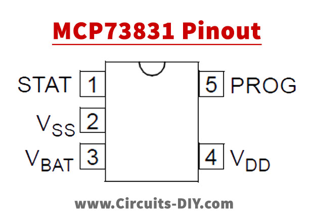
For a detailed description of pinout, dimension features, and specifications download the datasheet of MCP73831
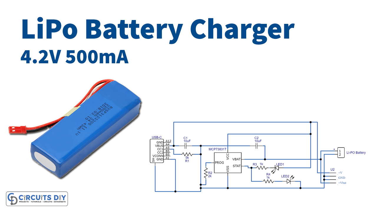
LiPo Battery Charger Circuit
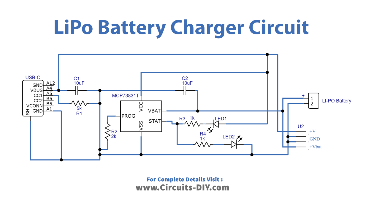
Working Explanation
To make the LiPo Battery Charger Circuit, we have used the MCP73811 microchip, having five pins, and with the help of them, it provides constant current and voltage operations with a tight regulation tolerance. When the liPo battery cell is connected to this microchip IC through the current regulation pin PROG, it sets the input function. Pin two is the battery management Vss that gets connected with the negative terminal or ground, while pin 4 vDd is a supply voltage. Pin 1 CE enables the active high charge and pin 3 VBAT gets connected to the positive of the connector. After these connections, the battery starts to charge.
Application and Uses
This charger is used to charge the LiPo batteries in:
- Laptops.
- Drones.
- Medical appliances.
- Robots, etc.


