A LED sequencer circuit or a ring counter is generally constructed by combining a clock pulse with a counter circuit. Usually, the input clock can be of any type such as through discrete components, astable multivibrator, inverter, logic gate, or dedicated timer IC such as a 555.
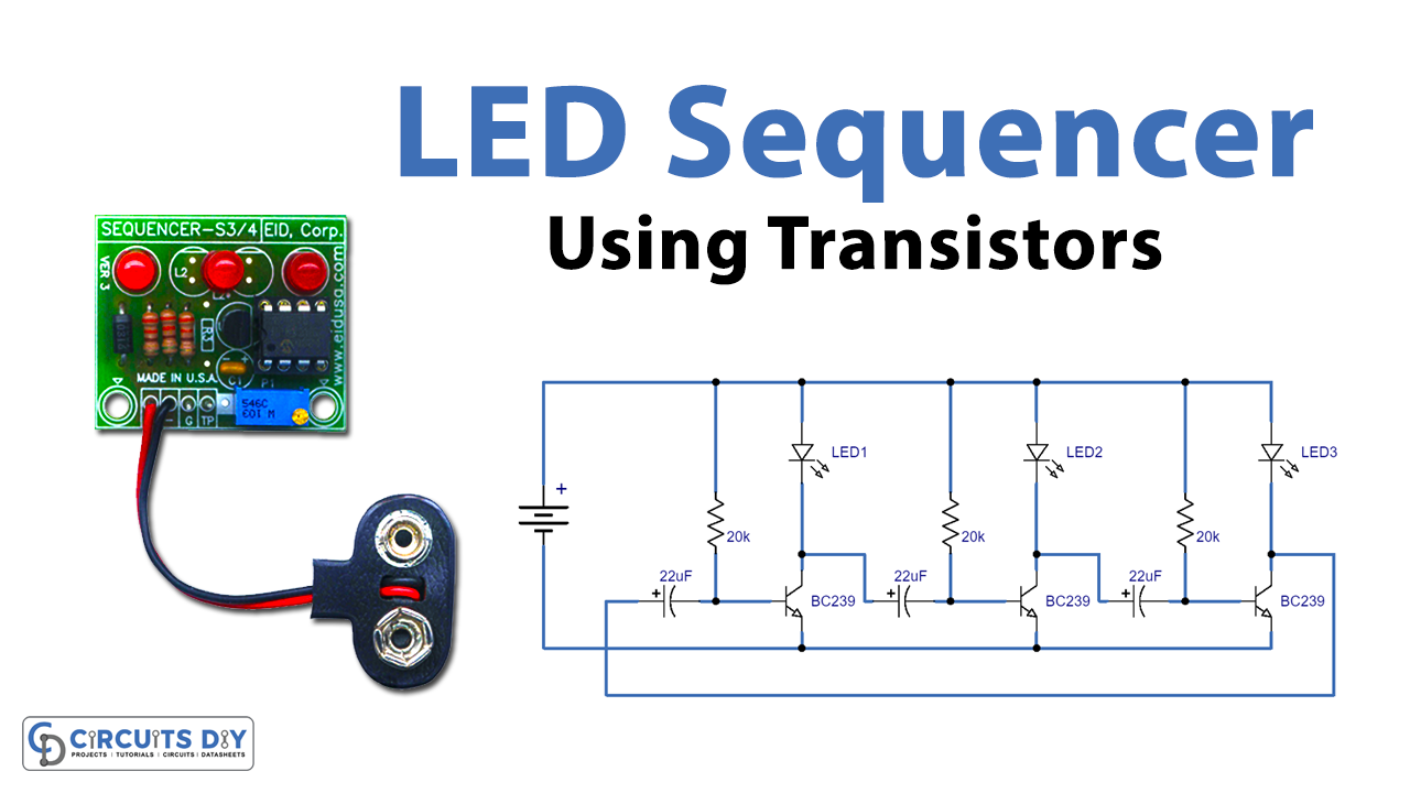
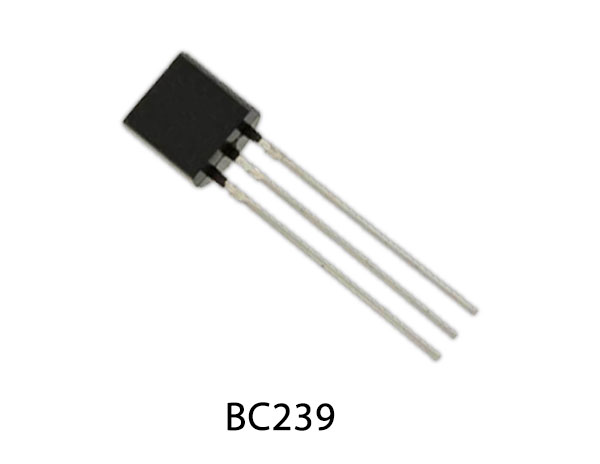
The counter can also be of any type such as 4-bit, 8-bit, decade, or shift registers. Discrete components can also be put together to make LED sequencers depending on capacitor charge times and transistor biasing. So, in this project, we are going to build a LED sequencer circuit using BC239 NPN transistors
Hardware Required
The following components are required to make LED Sequencer Circuit
| S.no | Component | Value | Qty |
|---|---|---|---|
| 1. | NPN Transistor | BC239 | 3 |
| 2. | LEDs | – | 3 |
| 3. | Resistors | 20K | 3 |
| 4. | Capacitors | 22uF | 3 |
| 5. | Battery | 3V | 1 |
| 6. | Battery Clips | – | – |
| 7. | Breadboard | – | 1 |
| 8. | Connecting Wires | – |
BC239 Pinout
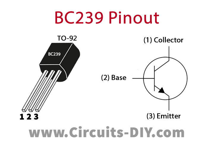
For a detailed description of pinout, dimension features, and specifications download the datasheet of BC239
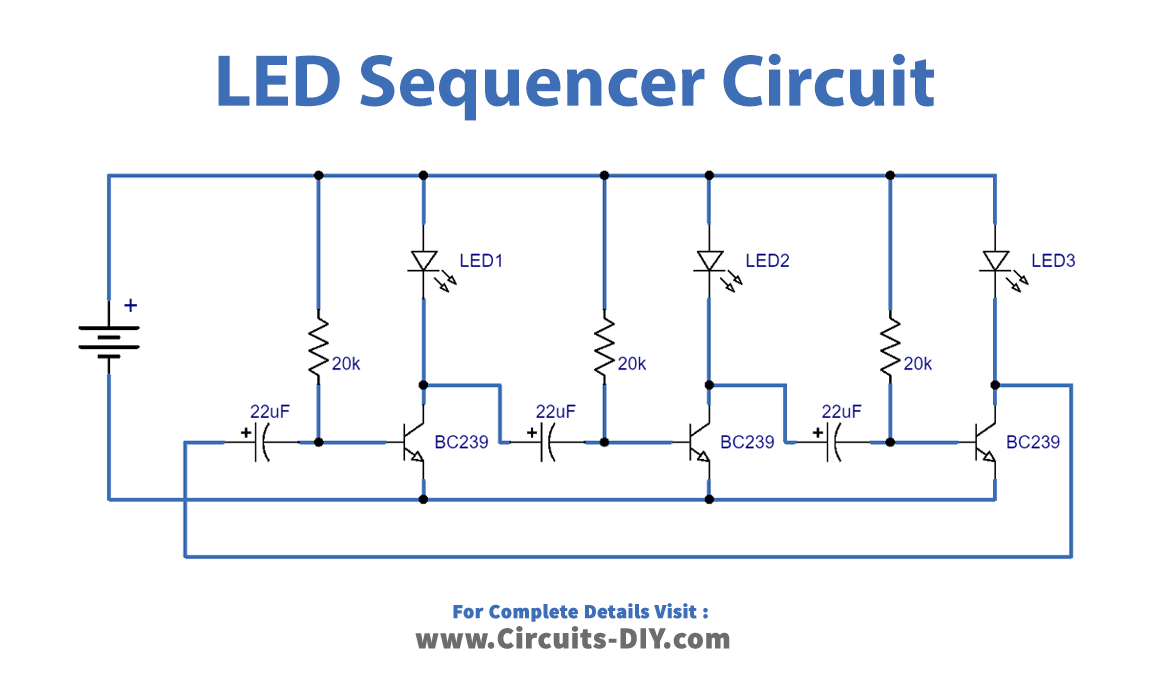
LED Sequencer Circuit
Working Explanation
The operation of this circuit is very simple. On completing the circuit, the 3V DC signal acts as a control signal on the base of the 1st transistor & the first led turns on. Then the DC output from the collector of the 1st transistor acts as the control signal for the base of the 2nd transistor and the 2nd LED turns on, after a fixed time delay due to the capacitor (22uF).
Then the output of the 2nd transistor goes to the base of the 3rd transistor & the 3rd led turns on. The collector output of the 3rd transistor loops back to the base of the 1st transistor to act as a control signal. Therefore, the LED sequencer continues to operate in a loop until the circuit power is cut-off.
Applications
- Widely used in places such as advertising displays and in running-light ‘rope’ displays in small discos, etc.
- Useful in various projects such as Remote controlled Switch, Alarm, Touch ON-OFF switch, Clap switch, Matrix Die.


