Introduction
Interfacing a 4×4 matrix keypad and a 16×2 LCD display with an Arduino UNO microcontroller is a simple and effective way to create a user-friendly interface for various applications. The keypad provides a convenient way for the user to input data, while the LCD display is used to display the results of the inputs. The combination of these two components, along with the Arduino UNO, makes it easy to create a system that can be used for a variety of purposes such as password protection, menu-driven systems, data input, and more.
A 4×4 matrix keypad module is a type of input device used in microcontroller-based systems. It consists of 16 buttons arranged in a 4×4 matrix configuration, where each row and column is connected to a digital input/output pin on a microcontroller. The keypad is used for data entry, navigation, and other purposes, and is often used in combination with a display such as an LCD or OLED screen. When a button is pressed, the microcontroller reads the corresponding row and column values and maps them to a specific key code, allowing the system to detect which button was pressed.
Hardware Components
You will require the following hardware for Interfacing LCD with Keypad
| S.no | Component | Value | Qty |
|---|---|---|---|
| 1. | Arduino UNO | – | 1 |
| 2. | USB Cable Type A to B | – | 1 |
| 3. | LED | I2C | 1 |
| 4. | Keypad 3×4 and 4×4 Kit | – | 1 |
| 5. | Power Adapter for Arduino | 9V | 1 |
| 6. | Jumper Wires | – | 1 |
Keypad LCD with Arduino
- Include the libraries for the Keypad and LCD modules:
#include <Keypad.h>
#include <LiquidCrystal_I2C.h>
- Define the keypad and LCD connections:
const byte ROWS = 4;
const byte COLS = 4;
char keys[ROWS][COLS] = {
  {'1', '2', '3', 'A'},
  {'4', '5', '6', 'B'},
  {'7', '8', '9', 'C'},
  {'*', '0', '#', 'D'}
};
byte rowPins[ROWS] = {5, 4, 3, 2};
byte colPins[COLS] = {9, 8, 7, 6};
Keypad keypad = Keypad(makeKeymap(keys), rowPins, colPins, ROWS, COLS);
LiquidCrystal_I2C lcd(0x3F, 16, 2); // I2C address 0x3F, 16 columns and 2 rows
- Define the setup function:
void setup() {
  lcd.begin(); // initialize the lcd
  lcd.backlight(); // turn on the backlight
  lcd.clear(); // clear the display
  lcd.setCursor(0, 0); // start to print at the first row
}
- Define the loop function:
void loop() {
  char key = keypad.getKey();
  if (key) {
    lcd.print(key); // print the key on the lcd
  }
}
Schematic
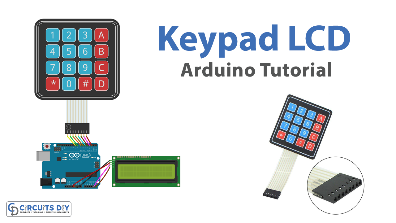
Make connections according to the circuit diagram given below.

Wiring / Connections
| Arduino | 4X4 Keypad | 16X2 LCD |
|---|---|---|
| 5V | VCC | |
| GND | GND | |
| A4 | SDA | |
| A5 | SCL | |
| D2 | R1 | |
| D3 | R2 | |
| D4 | R3 | |
| D5 | R4 | |
| D6 | C1 | |
| D7 | C2 | |
| D8 | C3 | |
| D9 | C4 |
Installing Arduino IDE
First, you need to install Arduino IDE Software from its official website Arduino. Here is a simple step-by-step guide on “How to install Arduino IDE“.
Installing Libraries
Before you start uploading a code, download and unzip the following libraries at /Progam Files(x86)/Arduino/Libraries (default), in order to use the sensor with the Arduino board. Here is a simple step-by-step guide on “How to Add Libraries in Arduino IDE“.
Code
Now copy the following code and upload it to Arduino IDE Software.
#include <Keypad.h>
#include <LiquidCrystal_I2C.h>

const int ROW_NUM    = 4; // four rows
const int COLUMN_NUM = 4; // four columns

char keys[ROW_NUM][COLUMN_NUM] = {
  {'1','2','3', 'A'},
  {'4','5','6', 'B'},
  {'7','8','9', 'C'},
  {'*','0','#', 'D'}
};

byte pin_rows[ROW_NUM] = {9, 8, 7, 6};      // connect to the row pinouts of the keypad
byte pin_column[COLUMN_NUM] = {5, 4, 3, 2}; // connect to the column pinouts of the keypad

Keypad keypad = Keypad(makeKeymap(keys), pin_rows, pin_column, ROW_NUM, COLUMN_NUM );
LiquidCrystal_I2C lcd(0x27, 16, 2); // I2C address 0x27, 16 column and 2 rows

int cursorColumn = 0;

void setup(){
  lcd.init(); // initialize the lcd
  lcd.backlight();
}

void loop(){
  char key = keypad.getKey();

  if (key) {
    lcd.setCursor(cursorColumn, 0); // move cursor to   (cursorColumn, 0)
    lcd.print(key);                 // print key at (cursorColumn, 0)

    cursorColumn++;                 // move cursor to next position
    if(cursorColumn == 16) {        // if reaching limit, clear LCD
      lcd.clear();
      cursorColumn = 0;
    }
  }
}
Working Explanation
The setup() function in the code for interfacing a 4×4 Arduino matrix keypad with a 16×2 Arduino LCD module involves initializing the LCD module by setting the appropriate communication protocol (I2C or SPI) and initializing the pins for the row and column connections of the matrix keypad.
The loop() function in the code for interfacing a 4×4 Arduino matrix keypad with a 16×2 Arduino LCD module is where the actual interaction between the keypad and LCD takes place. The function checks each row and column of the matrix keypad to see if a button has been pressed. If a button press is detected, the corresponding character is displayed on the LCD screen.
Applications
- Password protection systems
- Data entry systems
- Menu driven interfaces
- Pin code verification systems
- Number pad systems
- Keypad operated locks
- Calculators
- Keypad input for microcontroller-based projects.
Conclusion.
We hope you have found this Keypad LCD Arduino Circuit very useful. If you feel any difficulty in making it feel free to ask anything in the comment section.


