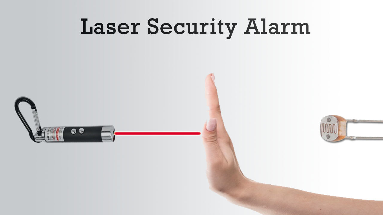
The laser security alarm circuit utilizes laser sensors for intruder detection. The main components of the laser security alarm circuit are infrared motion sensors and an alarm unit. It works by heat detection radiating from a person’s body. The circuit uses laser light and gets activated whenever any person crosses it.

Hardware Components
The following components are required to make Laser Security Alarm Circuit
| S. NO | Component | Value | Qty |
|---|---|---|---|
| 1. | Breadboard | – | 1 |
| 2. | Battery | 9v | 1 |
| 3. | Connecting Wires | – | 1 |
| 4. | IC | NE555 Timer | 1 |
| 5. | IC | LM358 | 1 |
| 6. | Laser Light Source | – | 1 |
| 7. | POT | 10K | 1 |
| 8. | Resistors | 150, 10k ohm | 2, 3 |
| 9. | Capacitor | 220uF | 1 |
| 10. | LDR | – | 1 |
| 11. | LED | 5mm | 1 |
555 IC Pinout

For a detailed description of pinout, dimension features, and specifications download the datasheet of 555 Timer
LM358 Pinout

For a detailed description of pinout, dimension features, and specifications download the datasheet of LM358
Laser Security Alarm Circuit
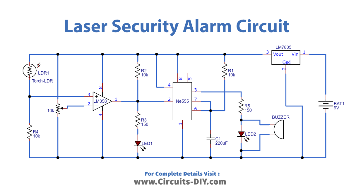
For circuit construction, we will use Dual Comparator IC LM358 to compare voltages received by LDR. Comparator IC LM358 is configured in a non-inverting mode with a 10K potentiometer connection at its non-inverting terminal. LDR will detect laser light in response to heat detection The midpoint of LDR and 10K potentiometer connects to the inverting terminal of IC LM358. The output pin of the comparator IC is connected to LED and indicates any intruder’s detection. The circuit is powered by a 9-volt battery.
Working Explanation
- Reference voltages of the comparator are set by using a 10 K potentiometer
- Comparator IC configures in a non-inverting mode.
- Laser light and LDR are placed in front of each other.
- Laser light falls on LDR.
- A potential difference is generated across the non-inverting pin of the comparator IC.
- The comparator compares this potential difference against the reference voltage and in response it generates a high digital output.
- Timer IC 555 is configured in mono-stable mode and is triggered by a low pulse to activate the LED.
- The comparator’s output is fed IC 555 timer.
- When the comparator’s output is HIGH, laser lights fall on LDR, deactivating the buzzer and LED.
- If someone crosses the laser light path a potential difference is generated across the same comparator terminal.
- Thus, the comparator generates a low output.
Applications
- Used for security arrangements for buildings, homes, apartments, and working places.
- Used in safety lockers