Introduction
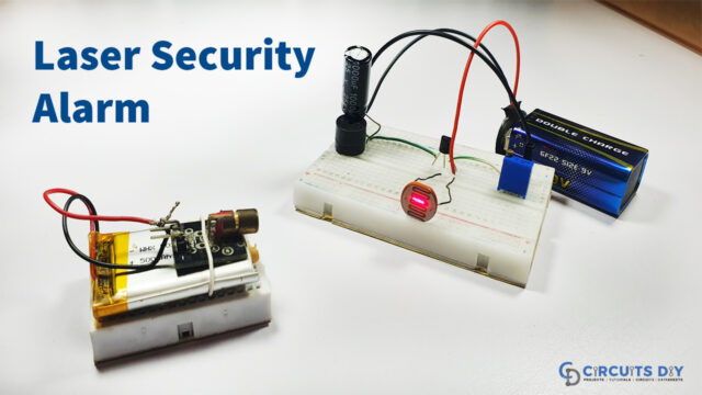
The term “laser” does not require an explanation. It is widely used in a variety of sectors. If you’re a student or perform document-related work, you’ve probably seen lasers in printers; if you’re a doctor, you’ve probably heard of laser therapy; and if you work in an industry, you’ve probably seen laser cutting. As a result, laser technology has a wide range of applications. But, have you ever thought that we can use it for security purposes? If not, then keep reading this article. Because, in this tutorial, we are going to make a “Laser Security Alarm Circuit”.
Along with the laser, the circuit uses the LDR as its key component. The electrical characteristic of the LDR is where the light increases, and its resistance decreases. Because of the higher resistance, the circuit does not operate until the light falls on the LDR. When there is no light, circuit functions are required.
Hardware Required
| S.no | Component | Value | Qty |
|---|---|---|---|
| 1. | LDR | – | 1 |
| 2. | NPN Transistor | BC548 | 2 |
| 3. | Buzzer | – | 1 |
| 4. | Switch | – | 1 |
| 5. | Resistor | 100 Ohm | 4 |
| 6. | Battery | 9V | 1 |
| 7. | LED | – | 1 |
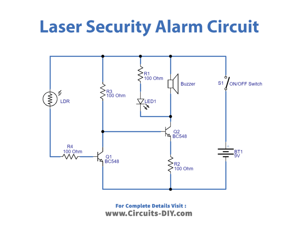
Circuit Diagram
Working Explanation
This Laser Security Alarm Circuit uses two BC548 NPN transistors as a switching device. Since the LDR is connected to the base terminal of the Q2 transistor through the R4 resistor, so it gives low resistance when laser light falls on it and high resistance when no laser light falls on it. The supply voltage to the Q2 transistor varies depending on the LDR resistance.
We wired the buzzer and LED to the collector terminal of the Q1 transistor, and we connected the base terminal of the Q1 transistor to the collector terminal of the Q2 transistor. Each transistor requires a threshold voltage to turn on.
If the laser light falls on the LDR, it allows voltage to the Q2 base, causing it to turn on; however, the Q1 transistor base does not receive any bias, resulting in the Q1 transistor remaining in the OFF state, resulting in the buzzer and LED remaining in the OFF state.
When the laser light is stopped, the LDR becomes high resistance, and no current flows to the Q2 transistor base, causing the Q2 to switch off. However, the Q1 transistor base power supply through the R3 resistor, causing the buzzer and LED to turn on, providing an alarm sound and indication.
Application and Uses
- Door security alarm
- Motion detection circuits
- Home or office security systems.
- Tripwire alarm circuits.
- Burgler/Intruder alarms.
- Security devices.
- Home and industrial automation systems.