Introduction
The assembly of SMT components by JLCPCB is more trustworthy and efficient. It does, however, need a thorough understanding of the entire procedure. It also includes requirements for the design phase. SMT creates designs that are both productive and effective. It can put together more components in a smaller space. As a consequence, money is saved and errors are reduced. However, it continues to expand daily. We anticipate that it will continue to improve in the future. Yet, it must be correctly manufactured using competent designers and top-of-the-line equipment.
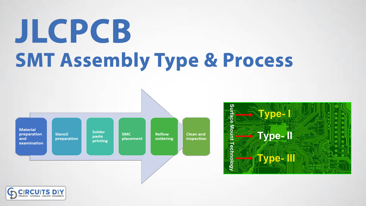
JLCPCB SMT Assembly Types
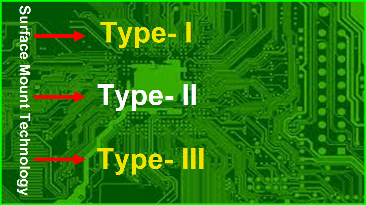
There are two methods or techniques of surface mount technology assembly.
- Type 1A and 1B Assembly
- Type 2 Assembly
1A Assembly
In this, surface mount components are only soldered on the component side of the printed circuit board. The steps include the paste application, placement, Preheating, and then cleaning.
Type 1B Assembly
In this type, components can be connected on either side of the boards. An adhesive application is needed after the paste is applied on the secondary side. However, it can be avoided by using low melting point solder on the other side of the board.
Type 2 Assembly
On this primary side have both through-hole and surface mount components are attached. But, the secondary side has only surface-mount elements. Since it is the assembly of mixed components. Therefore, it includes more operations and time.
JLCPCB Assembly Process

Material Preparation
To begin, they inspect the PCBs and electrical components to ensure that they fulfill the appropriate standards, then construct the SMC and PCB and test them for any flaws.
Stencil formulation
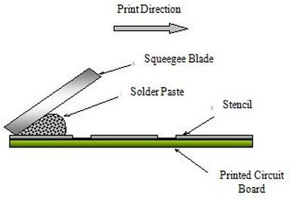
To apply solder paste, a stencil is utilized to keep the layout consistent. It is made following the solder pads used in the PCB layout. This function is carried out using a stencil printer. Depending on the board design, several steel stencils are utilized.
A PCB stencil, solder paste stencil, or laser stencil are all terms used to describe a surface mount technology (SMT) stencil. The main purpose of an SMT stencil is to transfer solder paste to a bare circuit board. Each surface mount device on the board has an opening created by a laser-cut stainless steel foil. The solder paste is put over the openings once the printed circuit board (PCB) stencil is properly aligned with the top of the board (in a single pass, with a metal squeegee). When the stainless steel foil peels away from the board, solder paste remains, ready for the surface-mount device to be manufactured (SMD). This method, as opposed to human soldering, maintains uniformity and saves time.

Solder Paste
The printing of solder paste is an important aspect of the SMT (Surface Mount Technology) process. The solder paste is fluid throughout the printing process because it is a blend of powder and flux. Solder paste has been used to link the PCB’s solder pads to selected SMCs. It’s made up of tin and flux. To apply solder paste using a stencil on the PCB, squeegee and silk-screening methods are utilized.
SMT Placement
The printed PCBs are then transported to the pick-and-place machines, where they are positioned on a conveyor belt with the electronic components.

Reflow Soldering
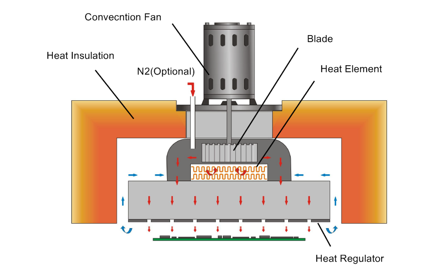
Preheat, thermal soak, reflow, and cooling are the four steps of the reflow solder process. The goal of the preheating stage is to evenly distribute heat across the board and components. The temperature gradient is critical because overly rapid temperature fluctuations can harm components.
The flux is initiated during the thermal soak to decrease oxidation of component pads and leads and promote wetting. The solder paste is melted in the third stage, and the process achieves its maximum temperature. This maximum temperature must stay below the components’ maximum allowable temperature. The maximum temperature will be determined by the component with the lowest maximum temperature allowed.
In the last zones of the reflow oven, the processed board cools down, the solder alloy solidifies, and the solder connections are formed. Unoptimized reflow profiles or methods might result in poor or non-wetting, damaged components, or cold soldering.
Inpection
New materials, new technology, and new equipment for SMT (Surface Mount Technology) assembly are continually emerging as the fundamental technology utilized in modern electronics production, with assembly density increasing, pin count increasing, and pitch decreasing. Furthermore, a growing number of SMDs (Surface Mount Devices) rely on visionless pins as packaging.
All of the abovementioned developments raise the bar for inspections and tests used in the SMT assembly process, making it increasingly important to establish inspection and test methods and select inspection technologies during SMT assembly.
Why JLCPCB SMT ?
- The setup charge is low; starting from $7.00, the stencil fee is $1.50, and the assembly fee is $0.0015 per joint.
- In 24 hours, you may assemble a prototype SMT board. Faster than ever before, get your items to market.
- JLCPCB has 230k+ SMD components in stock. Set you free from having to buy parts from several other vendors.
- There are no short leads on the components. The circuits’ parameter distribution is inherently reduced, and RF interference is similarly low.
- As a result of improved production equipment and reduced packaging material use, most SMT components are less expensive to package than THT components of the same type and function
- Component failure due to the welding process will be reduced, and reliability will increase, thanks to the standardisation, serialisation, and consistency of welding conditions of SMT components.


