
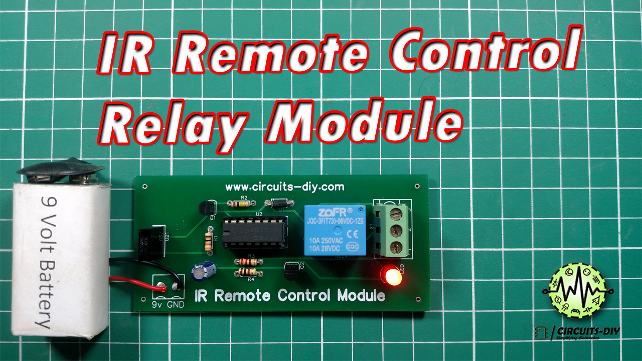
Wireless control using IR has become a popular trend in today’s electronics. Remote controllers using IR can control a wide array of devices as the working of these remotes is such that a light beam is emitted out by the remote and is received by a phototransistor. So, today in this tutorial, we are going to design an IR remote control switch using a CD4017 Decade counter IC.
The main component of this IR remote control switch Circuit is a CD4017 IC. A CD4017 IC is a 16-pin CMOS decade counter/Divider with 10 outputs. It is also known as the ‘Johnson 10 stage decade counter’. It has 10 decoded outputs that give output signals one by one in sequence when a clock signal from the clock input is given.
To activate the circuit, the remote and the circuit should be within the range of 8 meters. The IR receiver in this circuit is TSOP 1738, which is capable of receiving signals with a frequency range of 36 kHz to 38 kHz. The output of TSOP is active low, which means it will become LOW when IR is detected.
Hardware Components
The following components are required to make IR Remote Control Circuit
| S.No | Component | Value | Qty |
|---|---|---|---|
| 1 | Decade Counter IC | CD4017 | 1 |
| 2 | IR Receiver | TSOP1738 | 1 |
| 3 | RC IR Transmitter | – | 1 |
| 4 | 3-terminal connector | – | 1 |
| 5 | SPDT Relay | 5V | 1 |
| 6 | IC Jacket | 16 pin | 1 |
| 7 | Transistor (NPN, PNP) | BC547, BC557 | 1 |
| 8 | Diode | 1N4007 | 1 |
| 9 | LED | 5mm | 1 |
| 10 | Capacitor | 1uF | 1 |
| 11 | Resistor | 220, 1k, 10k, 100k | 4 |
| 12 | DC Battery | 9V | 1 |
| 13 | Battery Clip | – | 1 |
CD4017 Pinout
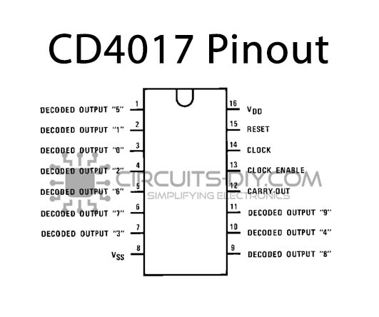
For a detailed description of pinout, dimension features, and specifications download the datasheet of CD4017
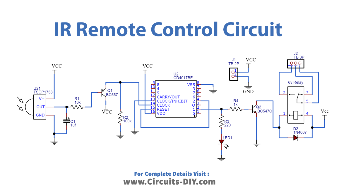
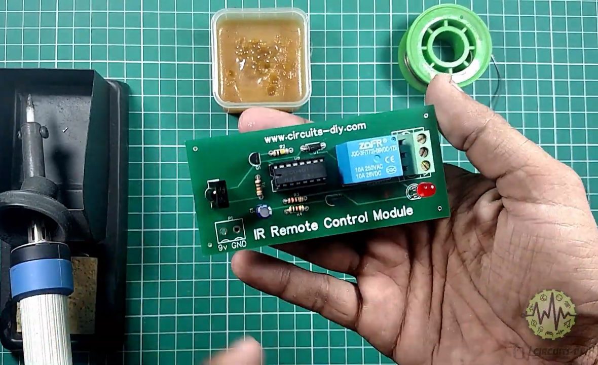
IR Remote Control Circuit
Connections
Follow the steps as shown in the video above.
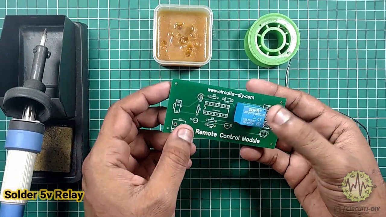
1) Solder the 5V SPDT relay on the PCB board
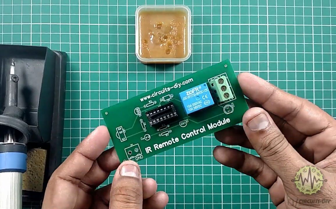
2) Solder the 16-pin IC jacket & the 3-pin terminal connector onto the PCB board.
3) Solder the transistors (BC547 & BC557) on the PCB Board.
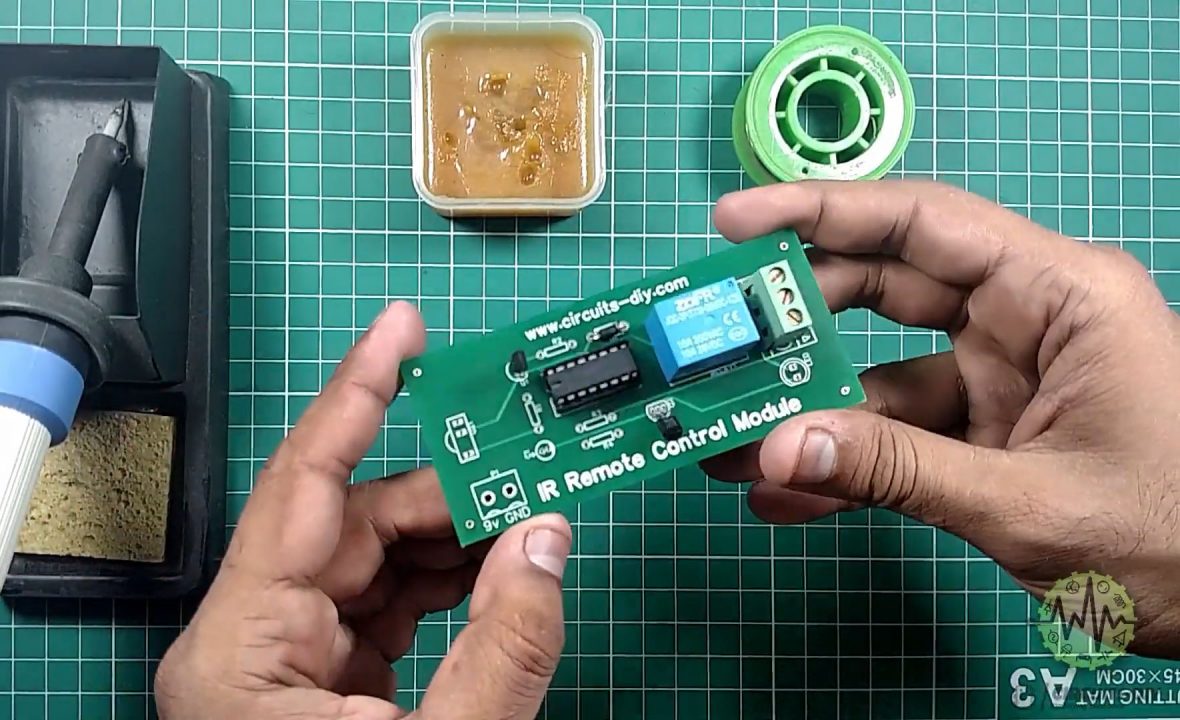
4) Solder all capacitors & resistors
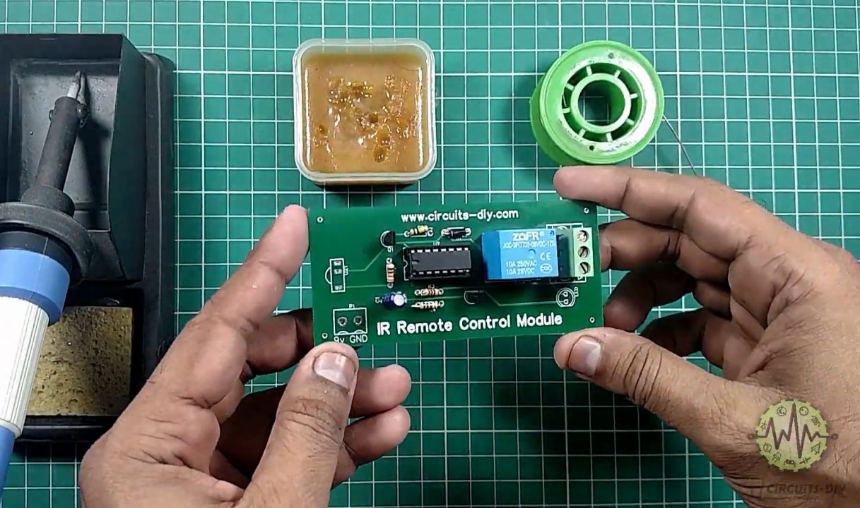
5) Solder the TSOP1738 & the output LED on the PCB board.
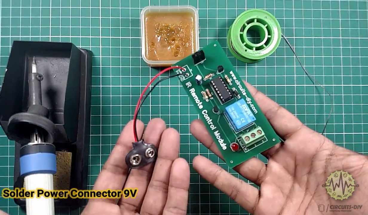
6) Solder the input connectors (Battery Clips) on the PCB board
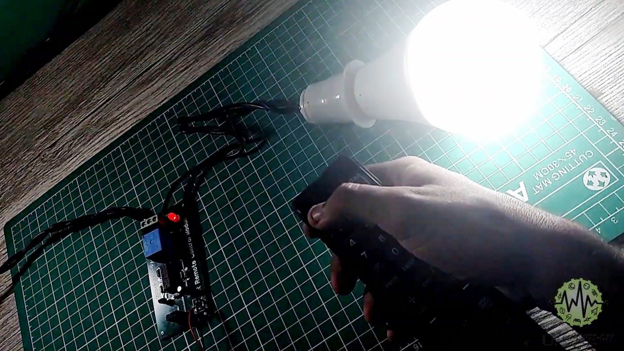
7) Connect AC Bulb carefully to the output of the 3-pin terminal.
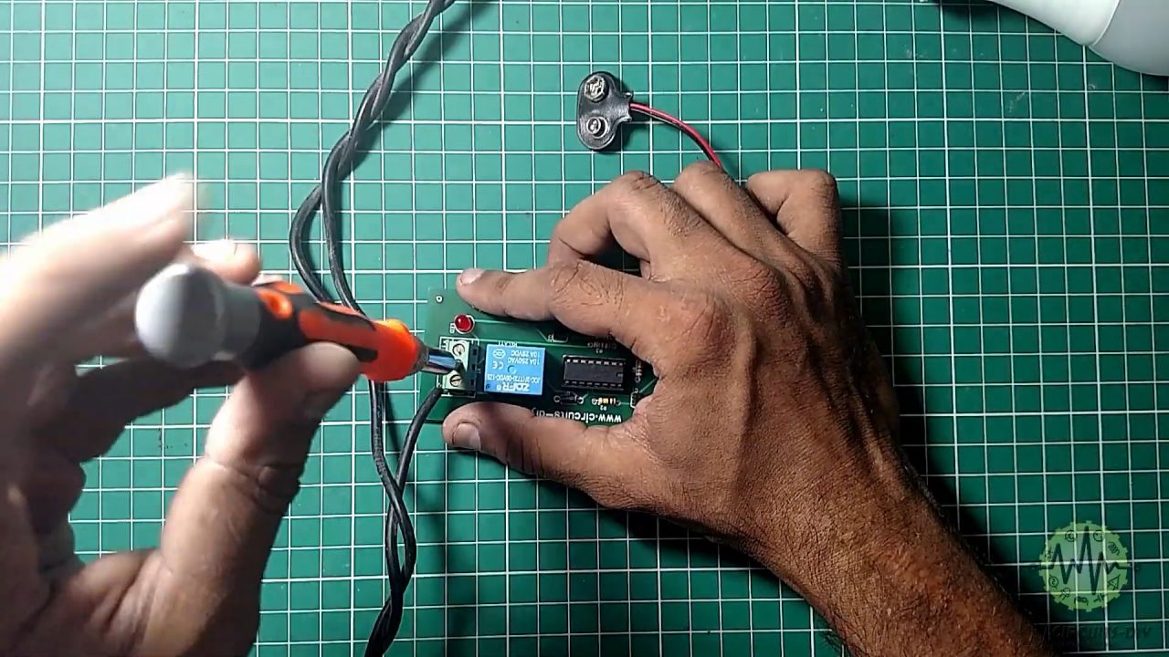
8) Test & Inspect the Circuit.
Working Explanation
The working of this circuit is quite simple. When an IR signal from a device such as a TV remote incidents on the IR receiver. The resultant output DC signal acts as a control signal to the base of the transistor Q1.
The collector output from the transistor serves as a clock input to Pin 14 (CLK) of the CD4017 setting the output Pin 2 to high. The output from the counter acts as a control signal to the base of the transistor Q2. The collector output from the transistor energizes the coil of the 5V SPDT Relay and completes the circuit of any external output device. Here, we are using a 1N4007 Diode to protect the relay from any shorts or negative feedback. The schematic & PCB .gbr files are provided at the end.
Application
- IR Doorbells & security alarms.
- Remote Control of Home Appliances


We are learning