
Introduction
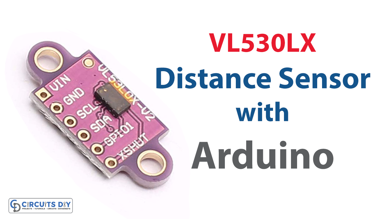
In this tutorial, we are Interfacing the VL530LX Laser Ranging Time of Flight Distance Sensor with Arduino. We previously have seen the distance measurement using ultrasonic sensors and IR sensors, here we use the time of flight sensor.
In contrast to sonars, which bounce ultrasonic waves, this sensor ‘cone’ is quite small. The time of flight sensor is significantly more accurate and doesn’t have linearity issues or double imaging, where you can’t distinguish if an object is extremely far or very close like IR distance sensors do, which attempt to detect the amount of light reflected.
What is the Laser Time of Flight Distance Sensor?
This laser time of light is a laser distance sensor with a wavelength of 940nm. It is highly precise and can measure distances up to some cm. It measures the “time of flight,” or how long it took the laser light to return to the sensor. It is effective for measuring distances of only the surface right in front of it since it employs a very narrow light source.

Hardware Components
You will require the following hardware for the Interfacing VL530LX Laser Ranging Time of Flight Distance Sensor with Arduino
| S.no | Component | Value | Qty |
|---|---|---|---|
| 1. | Arduino UNO | – | 1 |
| 2. | Laser Distance Sensor | VL53L0X | 1 |
| 3. | Breadboard | – | 1 |
| 4. | Jumper Wires | – | 1 |
Steps Interfacing Shooting Laser to Measure Distance
For the Interfacing VL530LX Laser Ranging Time of Flight Distance Sensor with Arduino, the list of necessary components is given in the table above. Once you get them all, take the following steps
Schematic
Make connections according to the circuit diagram given below.

Wiring / Connections
| Arduino | VL53L0X Sensor |
|---|---|
| 5V | VCC |
| GND | GND |
| A4 | SDA |
| A5 | SCL |
Installing Arduino IDE
First, you need to install Arduino IDE Software from its official website Arduino. Here is a simple step-by-step guide on “How to install Arduino IDE“.
Installing Libraries
Before you start uploading a code, download and unzip the following libraries at /Progam Files(x86)/Arduino/Libraries (default) to use the sensor with the Arduino board. Here is a simple step-by-step guide on “How to Add Libraries in Arduino IDE“.
Code
Now copy the following code and upload it to Arduino IDE Software.
#include "Adafruit_VL53L0X.h"

Adafruit_VL53L0X lox = Adafruit_VL53L0X();

void setup() {
  Serial.begin(115200);

  // wait until serial port opens for native USB devices
  while (! Serial) {
    delay(1);
  }

  Serial.println("Adafruit VL53L0X test");
  if (!lox.begin()) {
    Serial.println(F("Failed to boot VL53L0X"));
    while(1);
  }
  // power
  Serial.println(F("VL53L0X API Simple Ranging example\n\n"));
}


void loop() {
  VL53L0X_RangingMeasurementData_t measure;

  Serial.print("Reading a measurement... ");
  lox.rangingTest(&measure, false); // pass in 'true' to get debug data printout!

  if (measure.RangeStatus != 4) {  // phase failures have incorrect data
    Serial.print("Distance (mm): "); Serial.println(measure.RangeMilliMeter);
  } else {
    Serial.println(" out of range ");
  }

  delay(100);
}
Let’s Test It
It’s now time to test the circuit. So, power up the Arduino, and open the serial monitor. place your hand above the sensor and you will see the readings coming to the serial monitor. If the readings are more than the defined range; you will see the monitor would print ‘out of range’.
Working Explanation
Let’s dig into the coding to understand the working:
- First Include the library for the VL53L0X sensor and then make an object of that library
- In the void setup, we initialize the Serial monitor and give a while condition to wait until the serial port opens for native USB devices. Then we print the ‘Adafruit VL53L0X test’ on the serial monitor and provide the condition that if it fails to boot; the serial monitor would print “Failed to boot VL53L0X”
- In the void loop, we measure the distance and print the reading if it is in the defined range; otherwise, it would print the phrase ‘out of range’
- We then give a little delay to get the next readings.
Applications
- Obstacle detection
- Distance measurement; etc
Conclusion.
We hope you have found this Circuit very useful. If you feel any difficulty in making it feel free to ask anything in the comment section.
Related posts:
 How to Interface BME680 Environmental Sensor with Arduino UNO
 Potentiometer Triggers Piezo Buzzer - Arduino Tutorial
 LED Fade by Potentiometer - Arduino Tutorial
 DHT22 Sensor Interfacing with Arduino
 How Soil Moisture Sensor Works and Interface it with Arduino UNO
 Ultrasonic Security System using HC-SR04 & Arduino


