Introduction
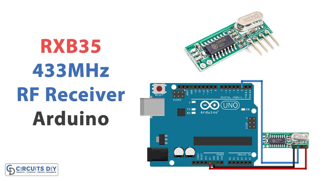
In this post, we will explore the RXB35 433MHz RF Receiver Module, a compact and highly efficient device allowing you to receive data wirelessly over the air using radio frequencies. RF receiver modules are electronic devices that receive and demodulate radio signals in a particular frequency range. They are commonly used in wireless communication systems to receive data transmitted over the air.
So, are you ready to join us on this exciting journey and discover the endless possibilities of wireless communication? Let’s get started!
What is RF Receiver Module?
The process of receiving and demodulating radio frequency signals requires employing a device known as an RF receiver module. It is often used in wireless communication systems to receive and process incoming radio frequency signals.
Hardware Components
You will require the following hardware for Interfacing RXB35 433MHz RF Receiver Module with Arduino.
| S.no | Component | Value | Qty |
|---|---|---|---|
| 1. | Arduino UNO | – | 1 |
| 2. | Module | RXB35 433MHz | 1 |
| 3. | Breadboard | – | 1 |
| 4. | Jumper Wires | – | 1 |
RF Receiver Module with Arduino
Now that you have got all an understanding of the RF receiver module, you need to follow the given steps in order to interface it with Arduino.
Schematic
Make connections according to the circuit diagram given below.

Wiring / Connections
| Arduino | 433MHz Module |
|---|---|
| 5V | VCC |
| GND | GND |
| D2 | DATA |
Installing Arduino IDE
First, you need to install Arduino IDE Software from its official website Arduino. Here is a simple step-by-step guide on “How to install Arduino IDE“.
Installing Libraries
Before you start uploading a code, download and unzip the following libraries at /Progam Files(x86)/Arduino/Libraries (default), in order to use the sensor with the Arduino board. Here is a simple step-by-step guide on “How to Add Libraries in Arduino IDE“.
Code
Now copy the following code and upload it to Arduino IDE Software.
/*
  Simple example for receiving

  https://github.com/sui77/rc-switch/
*/

#include <RCSwitch.h>

RCSwitch mySwitch = RCSwitch();

void setup() {
  Serial.begin(9600);
  mySwitch.enableReceive(0);  // Receiver on interrupt 0 => that is pin #2
}

void loop() {
  if (mySwitch.available()) {

    int value = mySwitch.getReceivedValue();

    if (value == 0) {
      Serial.print("Unknown encoding");
    } else {
      Serial.print("Received ");
      Serial.print( mySwitch.getReceivedValue() );
      Serial.print(" / ");
      Serial.print( mySwitch.getReceivedBitlength() );
      Serial.print("bit ");
      Serial.print("Protocol: ");
      Serial.println( mySwitch.getReceivedProtocol() );
    }

    mySwitch.resetAvailable();
  }
}
Let’s Test It
Now would be a good time to put the circuit through its test. Thus, after you have uploaded the code to the Arduino board, the code will test the connection between the transmitter and the receiver. The receiver can see the transmitted data on the serial monitor.
Working Explanation
- The #include <RCSwitch.h> line is a directive that tells the compiler to include a specific file in the source code during the preprocessing stage. In this case, the RCSwitch library’s file is included, which provides functions for communicating with radio frequency (RF) devices using an Arduino board.
- The RCSwitch mySwitch = RCSwitch(); line creates an instance of the RCSwitch class called mySwitch. We will use this instance to access the functions of the RCSwitch library.
- The void setup() function is a special function in Arduino sketches that is called once when the sketch starts. In this function, the serial communication is initialized using Serial.begin(9600), and the mySwitch instance is configured to receive signals on interrupt 0, corresponding to pin #2 on the Arduino board.
- The loop() function is another special function in Arduino sketches that is called repeatedly after the setup() function has been completed. In this function, the code checks if any data is available for the mySwitch instance using mySwitch.available(). If data is available, the getReceivedValue() function is used to retrieve the value of the received signal, and the getReceivedBitlength() and getReceivedProtocol() functions are used to get the bit length and protocol of the signal, respectively. The received data is then printed to the serial port using Serial.print() and Serial.println(). In the end, the resetAvailable() function is called to reset the availability flag for the mySwitch instance.
Applications
- Wireless control network
- Remote control devices
- Wireless data transmission systems, etc
Conclusion.
We hope you have found this Interfacing RXB35 433MHz RF Receiver Module with Arduino Circuit very useful. If you feel any difficulty in making it feel free to ask anything in the comment section.