A rotary encoder is also called a shaft encoder. It is an electro-mechanical device, that converts the angular position or motion of a shaft or axle to an analog or digital output signal. There are two main types of rotary encoders: absolute and incremental. The output of an absolute encoder indicates the current shaft position, making it an angle transducer. The output of an incremental encoder provides information about the motion of the shaft, which typically is processed elsewhere into information such as position, speed, and distance. Rotary Encoders are useful for counting operations. This article will give basic Arduino rotary encoder interfacing details and the operation of conventional rotary encoders.
Hardware Required
| S.no | Component | Value | Qty |
|---|---|---|---|
| 1. | Arduino UNO | – | 1 |
| 2. | USB Cable Type A to B | – | 1 |
| 3. | Jumper Wires | – | – |
| 4. | Rotary Encoder | – | 1 |
Rotary Encoder

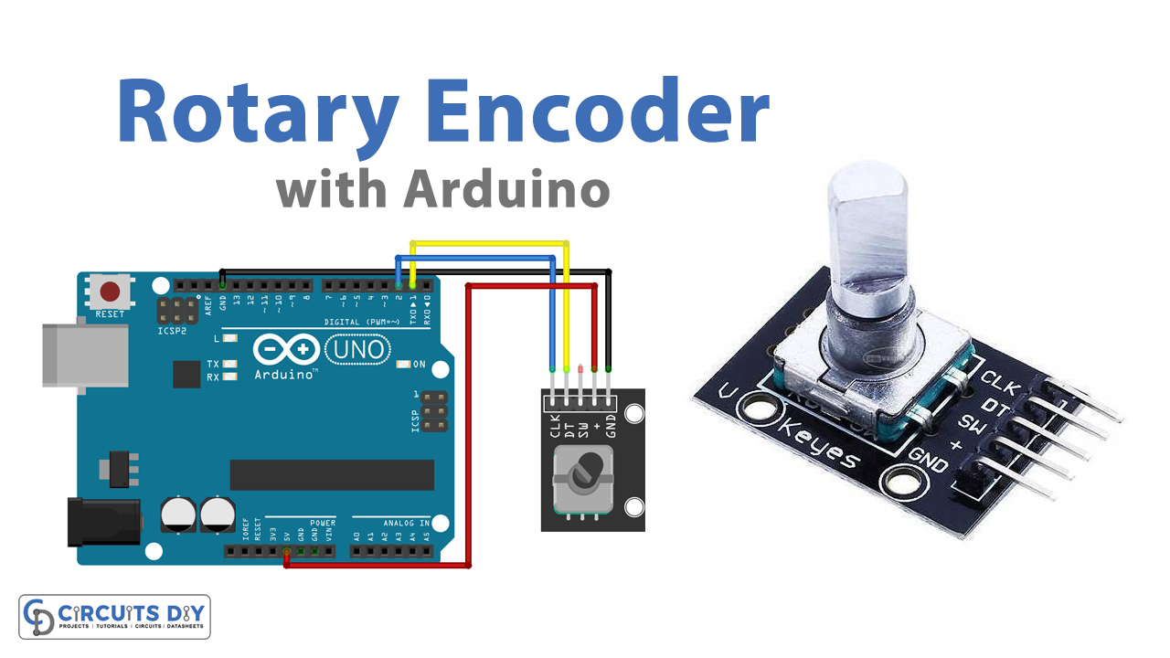
This rotary encoder breakout board has five pins,
- GND → Ground Supply
- + → +5V Power Supply
- SW → Button Switch
- DT → Encoder Pin B
- CLK → Encoder Pin A
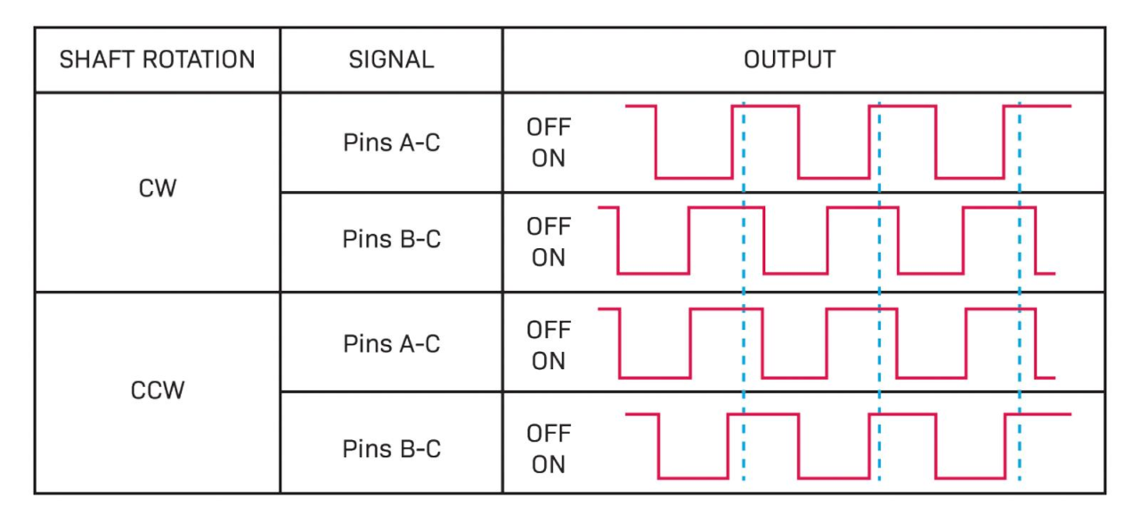
The output pulse is generated at encoder pin A with 90º out of phase from encoder pin B when the shaft is rotated clockwise.
And when the shaft is rotated counterclockwise then the output generated at the encoder output pins A & B are inverted.
Rotary Encoder Arduino Interface
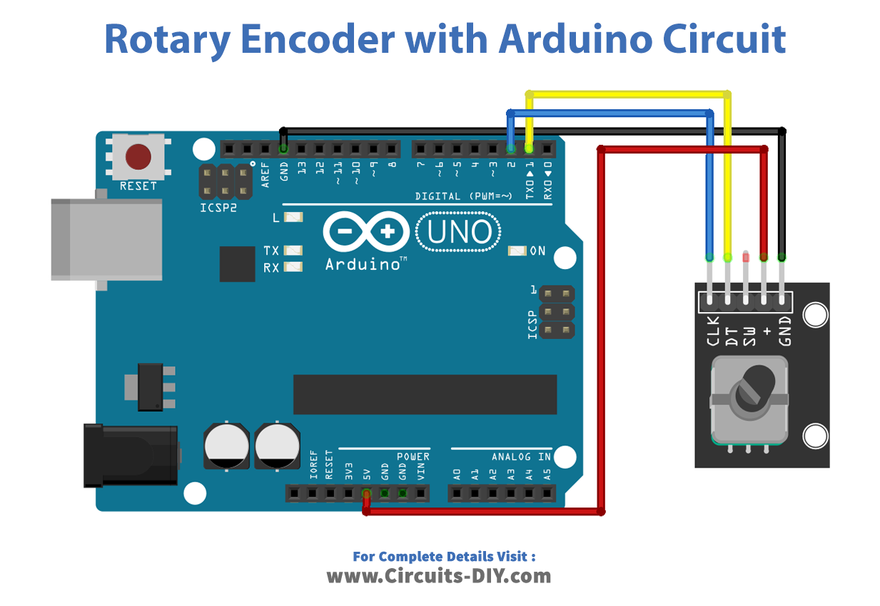
Here connect the power supply pins of the rotary encoder to the Arduino board as + to 5V and GND to GND. Then connect CLK (Encoder out A) pin to Arduino digital pin D2 and DT (Encoder out B) pin to digital pin D1. After completing the hookup, upload the following Sketch to get the angle and position of the rotary encoder in the serial monitor.
Arduino Sketch for Rotary Encoder
#define encoderOutA 2 // CLK pin of Rotary Enocoder
 #define encoderOutB 1 // DT pin of Rotary Enocoder

 int counter = 0;
 int presentState;
 int previousState;
 void setup() {
   pinMode (encoderOutA,INPUT);
   pinMode (encoderOutB,INPUT);

   Serial.begin (9600);
      previousState = digitalRead(encoderOutA);   // Get current state of the encoderOutA
 }
 void loop() {
   presentState = digitalRead(encoderOutA);
      if (presentState != previousState)
      {
          if (digitalRead(encoderOutB) != presentState)
          {
       counter ++;
     }
     else {
       counter --;
     }
     Serial.print("Position: ");
     Serial.println(counter);
   }
   previousState = presentState; // Replace previous state of the encoderOutA with the current state
 }
Code Explanation
First, define the output pins and initialize the count as 0, then declare the present & previous state variables.
In the “IF” condition loop, get the present state of the rotary encoder and compare it with the previous state. If there is no change then the count remains the same, else the count value increases for clockwise rotation and decreases for counterclockwise rotation.
Applications
Rotary encoders are used in a wide range of applications that require monitoring or control, or both, of mechanical systems, including industrial controls, robotics, photographic lenses, computer input devices such as optomechanical mice, and trackballs, controlled stress rheometers, and rotating radar platforms.


